Hummer H1 (2002+). Manual — part 57
____________________________________________
Transmission/Transfer Case 5-27
®
05745159
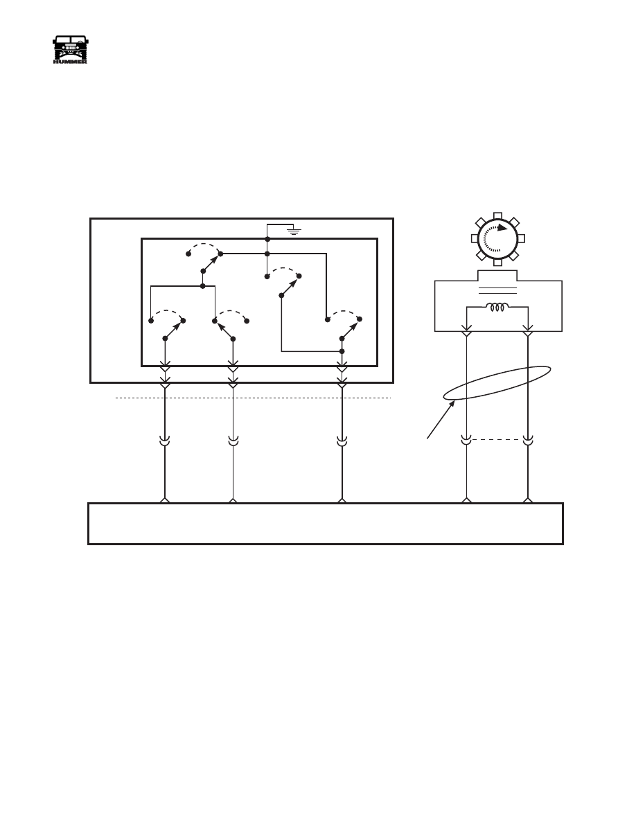
Figure 5-27: Transmission Wiring Diagrams 6 of 6
Automatic
Transmission
Fluid
Pressure
Manual Valve
Position
Switch
(TFP)
Trans
Range C
Input
Trans
Range B
Input
Trans
Range A
Input
C34
P
R
N
D
E
C
Rev
Switch
Lo
Switch
D2
Switch
D3
Switch
D4
Switch
C32-S
C32-H
C32-K
764 PP
763 DB
762 OR
C29-B4
C29-B5
C29-B6
A / T ISS
High
A / T ISS
Low
Tw i s t e d
P a i r
B
C32-A
B
A
Auto Trans Input Shaft
Speed Sensor
A/T ISS
C27-D1
C27-D11
495 DB
496 GY
POWERTRAIN
CONTROL
MODULE
(PCM)
9-S12-071
5-28
Transmission/Transfer Case
_____________________________________________
®
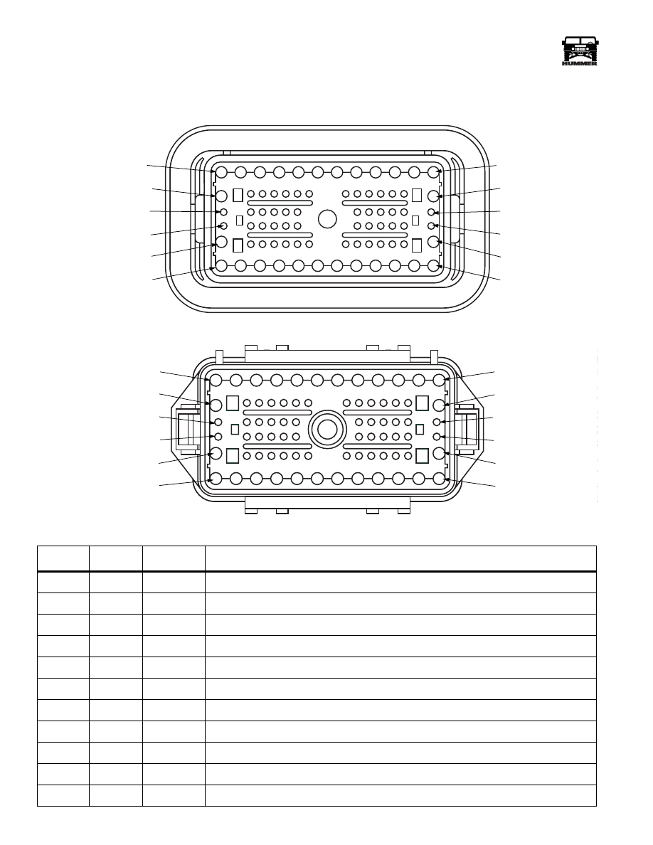
Connector Legend
76 WAY BULKHEAD LOCATION: LEFT SIDE FIREWALL
PIN
CKT
COLOR
CIRCUIT DESCRIPTION
1
400
LG
Ignition Feed +
2
739
PP
Left heated windshield power +
3
740
YL
Right heated windshield power +
4
43
DB
Trailer Brake activation
5
962
BR
Trailer lights
6
33
WH
neutral safety switch feed
7
37E
YL
start relay feed
8
37D
YL
Ignition switch feed
9
786
RD
Fuel selector valve control
10
537
OR
Battery
11
787
GY
Fuel pump + to selector valve
C1 MALE
9-S12-048
PIN 1
PIN 12
PIN 13
PIN 26
PIN 27
PIN 38
PIN 50
PIN 64
PIN 76
PIN39
PIN 51
PIN 65
C1 FEMALE
9-S12-047
CAV 1
CAV 13
CAV 27
CAV 39
CAV 51
CAV 65
CAV 12
CAV 26
CAV 38
CAV 50
CAV 64
CAV 76
____________________________________________
Transmission/Transfer Case 5-29
®
05745159
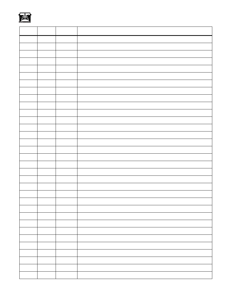
12
37
RD
Ignition relay feed
13
688
RD
Rear window defrost feed
14
723
YL
APP 3 5volt reference
15
724
DG
APP 3 signal
16
17
PP
+ From dimmer module
17
718
DB
APP 1 signal
18
353
YL
Speedometer signal
19
607
TN
ABS module diagnostic line
20
717
WH
APP 1 5-volt reference
21
961
PP
TT4 lamp activation
22
720
TN
APP 2 5-volt reference
23
640
OR
IGN+ CTIS warning circuits
24
92
GY
CTIS rear inflate solenoid activation
25
714
DB
Check throttle lamp activation
26
37
RD
Battery feed to interiror accessories
27
338
DB
Wait lamp activation
28
658
BR
Check engine lamp activation
29
151
GY
Cruise control ON/OFF signal
30
31
TN
Oil pressure signal
31
22
RD
Brake switch signal – rest
32
721
LB
APP 2 sensor signal
33
580
BR
Not Used for 99
34
606
OR
ABS diagnostic line
35
29
PK
Fuel guage signal
36
39
DG
Engine temperature signal
37
153
LG
Cruise resume/accelerate signal
38
42
BR
Low brake fluid lamp activation
39
198
TN
A/C request
40
810
PP
TCC brake switch signal
41
2
LG
Right front turn signal
42
152
DB
Cruise set/coast signal
43
298
BR
Backup light switch feed
44
722
PP
APP 2 ground
PIN
CKT
COLOR
CIRCUIT DESCRIPTION
5-30
Transmission/Transfer Case
_____________________________________________
®
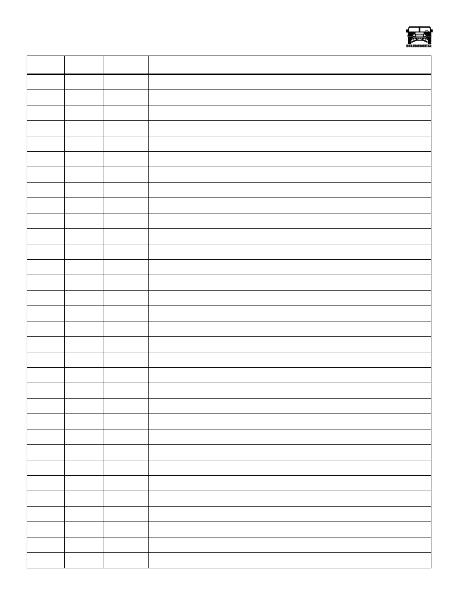
45
327
YL
Water-in-fuel lamp activation
46
80
WH
Underhood lamp power
47
3
LB
Left front turn signal
48
914
PP
PCM class 2 communication line to DLC
49
644
YL
Tachometer signal
50
210
DG
Low washer fluid level lamp activation
51
195
YL
Headlight switch feed
52
603
DG
ABS lamp activation
53
719
BR
APP 1 ground
54
793
YL
Low coolant lamp activation
55
794
RD
Low air warning lamp activation
56
41
TN
Brake fluid level sensor feed
57
428
PK
CTIS buzzer activation
58
47
LG
Deflate solenoid activation
59
46
WH
CTIS compressor relay activation
60
725
GY
APP 3 Ground
61
767
BR
Compass mirror temperature signal
62
1
DB
Horn relay activation
63
91
TN
CTIS front inflate solenoid activation
64
37
RD
Batt feed to interior fuse box
65
12
OR
Headlamp high beam feed
66
13
TN
Headlamp low beam feed
67
38
RD
Headlamp switch feed
68
16
LG
Ignition supply to exterior fuse box fuses 2A, 2B, and 3B
69
175
LB
Power window relay feed
70
943
BR
Upper windshield washer pump activation
71
5
DG
Right rear turn signal
72
9
YL
Left rear turn signal
73
20
RD
Front park lamps
74
21
GY
Rear tail lamp feed
75
789
BR
Fuel selector valve control
76
941
TN
Lower windshield washer pump activation
PIN
CKT
COLOR
CIRCUIT DESCRIPTION
Нет комментариевНе стесняйтесь поделиться с нами вашим ценным мнением.
Текст