Hummer H1 (2002+). Manual — part 73
____________________________________________
Transmission/Transfer Case 5-91
®
05745159
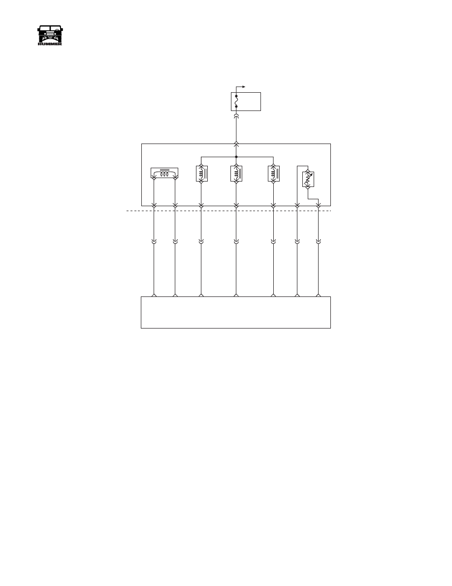
DTC P0751 1-2 Shift Solenoid
Valve Performance
Circuit Description
The 1-2 shift solenoid is used to control fluid acting on the 1-2
and 3-4 shift valves. The solenoid is a normally open valve
used with the 2-3 solenoid to allow four different shifting com-
binations.
This DTC detects incorrect Gear Ratios when a Gear is com-
manded. This is a type “A” DTC.
Conditions For Setting The DTC
• No DTCs P0121, P0122, P0123, P0220, P0221, P0222,
P0223, P0225, P0226, P0227 or P0228.
• No DTCs P0722 or P0723.
• No DTCs P0716 or P0717.
• No shift solenoid 1-2 DTC P0753.
• No shift solenoid 2-3 DTC P0758.
• No Pressure switch assembly DTC P1810.
• No Four Wheel Drive DTC P1875.
• Engine running.
• Vehicle speed is greater than 4.2 km/h (2.5 mph).
• Throttle angle is greater then 12%.
• Engine Torque between 60 ft/lbs and 450 ft/lbs.
• Transmission fluid temperature is greater than 20° C
(69° F).
• Engine Speed is less than 3650 RPM.
• Not in Four Wheel Drive Low.
FUSE 2A
10A
EXTERIOR
C33-F
351 PK
C34
D
C
S
B
A
M
L
C32-G
C32-F
C32-E
C32-D
C32-C
C32-J
C32-H
C34-E
C27-C15
C27-C7
C28-C5
C28-C6
C28-C4
C29-B12
C27-C9
265 LB
264 RD
924 TN
315 YL
237 LG
359 BK
923 BR
PRESSURE
CONTROL
SOLENOID
(PCS)
TORQUE
CONVERTER
CLUTCH
SOLENOID
(TCC)
1-2 SHIFT
SOLENOID
(1-2)
2-3 SHIFT
SOLENOID
(2-3)
TRANSMISSION
FLUID
TEMPERATURE
SENSOR
(TFT)
PCS
LOW
PCS
HIGH
TCC PWM
SOLENOID
CONTROL
2-3 SS
CONTROL
1-2 SS
CONTROL
SENSOR
GROUND
TFT
SENSOR
SIGNAL
POWERTRAIN
CONTROL
MODULE
(PCM)
HOT IN RUN
AND START
9 - S 1 2 - 0 6 7

5-92
Transmission/Transfer Case
_____________________________________________
®
Stuck Off: (after two occurrences)
• Ist gear is commanded and the ratio is equal to 2nd gear
for greater than 1.7 seconds.
• 4th gear is commanded (with converter clutch locked)
and ratio is equal to 3rd gear for greater than 3 seconds.
Stuck On: (after five occurrences)
• 2nd gear is commanded and the ratio is equal to 1st gear
for greater than 2.5 seconds.
• Condition is met with 5 occurrences.
Action Taken When The DTC Sets
• The PCM will command maximum line pressure.
• The PCM will freeze shift adapts.
• The PCM will turn on the warning lamp.
Conditions For Clearing The MIL/DTC
• The PCM will turn the warning lamp off after three con-
secutive ignition cycles without a failure reported.
• The DTC can be cleared using the scan tool.
• The PCM will cancel DTC default actions when the
fault no longer exists and ignition is cycled “off” long
enough to power down the PCM.
Diagnostic Aids
• Verify that the transmission meets the specifications in
the 4L80-E shift speed chart.
• Other internal transmission failures may cause more
than one shift to occur.
• If any engine DTCs or TPS codes are present diagnose
and clear these DTCs first.
Test Description
The numbers below refer to the diagnostic chart.
1.This test checks pressure switch function of the PSA.
2.This test checks that the scan tool commanded all shifts,
all shift solenoids responded correctly, but all the shifts
did not occur.
4L80-E CHART
Gear
1-2 Shift
Solenoid
2-3 Shift
Solenoid
1
ON
OFF
2
OFF
OFF
3
OFF
ON
4
ON
ON
DTC P0751 1-2 Shift Solenoid Valve Performance
Step
Action
Value
Yes
No
1
1.
Connect scan tool.
2.
Turn ignition switch on.
3.
Record DTC “Freeze Frame” and Failure Records.”
4.
Start engine, apply brake pedal and shift to follow-
ing ranges D1, D2, D3, D4, N, R, and P.
Does each transmission range match the “TR Switch”
on the scan tool?
—
Go to Step 2
Go to Pressure
Switch Assem-
bly (PSA)
Resistance
Check
2
1.
Raise vehicle on hoist that allows wheels to rotate.
2.
Start engine, shift into D4 range, use scan tool to
command 1st, 2nd, 3rd, and 4th gears increasing
speed.
Did 2-3 or 1-4 only shift pattern occur? (Road testing
may be necessary).
—
Go to Step 3
Go to Diagnos-
tic Aids
3
Check the shift solenoid/hydraulic circuit for:
• Shift solenoids for an internal malfunction.
• Damaged seals on the shift solenoids.
Was a problem found and corrected?
—
Go to Step 4
—
4
1.
After the repair is complete, use scan tool to select
“DTC” then “Clear Info” function.
2.
Select “Specific DTC” and enter DTC “P0751.”
3.
Operate the vehicle under the following conditions
• Hold the throttle at 20% and accelerate to 55 mph
(if the throttle moves more than 3%, stop the ve-
hicle and start over).
• PCM must see the proper ratio for each com-
manded gear for greater than one second in D1,
D2, D3, and D4.
—
—
Repair verified,
exist DTC
table.
____________________________________________
Transmission/Transfer Case 5-93
®
05745159
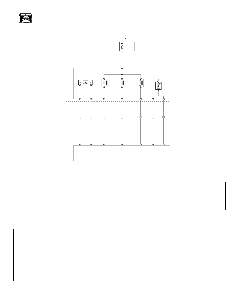
DTC P0753 1-2 Shift Solenoid Valve Electrical
Circuit Description
The 1-2 shift solenoid is used to control fluid acting on the 1-2 and
3-4 shift valves. The solenoid is a normally open valve used with
the 2-3 solenoid to allow four different shifting combinations. The
solenoid is attached to the control valve body. Ignition voltage is
supplied directly to the 1-2 shift solenoid. The PCM controls the
solenoid by providing a ground path through circuit 237.
This DTC detects a continuous open or short to ground in the 1-2
shift solenoid circuit or the 1-2 shift solenoid sensor.
Conditions For Setting DTC
• Ignition is on.
• The engine runs more then 475 RPM for greater than 7
seconds.
All conditions for running the DTC are met, and either of the
following conditions occur for 4.3 out of 5 seconds.
• The PCM commands the solenoid on, and the voltage
input remains high (B+).
• The PCM commands the solenoid off and the voltage
input remains low.
Action Taken When DTC Sets
• The PCM will command maximum line pressure.
• The PCM will freeze shift adapts.
• The PCM will turn on the warning lamp.
• The PCM will store a DTC P0753 in the PCM history.
Conditions For Clearing DTC
• For California emissions, the PCM will turn the warning
lamp off after three consecutive ignition cycles without a
failure reported.
• The DTC can be cleared using the scan tool. The DTC
will be cleared when the vehicle has achieved 40 warm-
up cycles without a failure reported.
• The PCM will cancel DTC default actions when the
fault no longer exists and the ignition is cycled “off”
long enough to power down the PCM.
FUSE 2A
10A
EXTERIOR
C33-F
351 PK
C34
D
C
S
B
A
M
L
C32-G
C32-F
C32-E
C32-D
C32-C
C32-J
C32-H
C34-E
C27-C15
C27-C7
C28-C5
C28-C6
C28-C4
C29-B12
C27-C9
265 LB
264 RD
924 TN
315 YL
237 LG
359 BK
923 BR
PRESSURE
CONTROL
SOLENOID
(PCS)
TORQUE
CONVERTER
CLUTCH
SOLENOID
(TCC)
1-2 SHIFT
SOLENOID
(1-2)
2-3 SHIFT
SOLENOID
(2-3)
TRANSMISSION
FLUID
TEMPERATURE
SENSOR
(TFT)
PCS
LOW
PCS
HIGH
TCC PWM
SOLENOID
CONTROL
2-3 SS
CONTROL
1-2 SS
CONTROL
SENSOR
GROUND
TFT
SENSOR
SIGNAL
POWERTRAIN
CONTROL
MODULE
(PCM)
HOT IN RUN
AND START
9 - S 1 2 - 0 6 7
3-1-01

5-94
Transmission/Transfer Case
_____________________________________________
®
Diagnostic Aids
• Inspect the wiring for poor electrical connections at the
PCM and at the transmission 20-way connector. Look
for possible bent, backed out, deformed or damaged ter-
minals. Check for weak terminal tension as well. Also
check for a chafed wire that could short to bare metal or
other wiring. Inspect for a broken wire inside the insula-
tion.
• When diagnosing for a possible intermittent short or
open condition, move or massage the wiring harness
while observing test equipment for a change.
• An open ignition feed circuit can cause multiple DTCs
to set.
• If any engine DTCs or TPS codes are present diagnose
and clear these DTCs first. Then check to see if the
transmission DTCs have reset.
Test Description
The numbers below refer to the step numbers on the diagnostic
chart.
3. This test checks the function of the 1-2 shift solenoid
and the internal wiring harness.
5. This test checks for power to the 1-2 shift solenoid
from the ignition through the fuse.
13. This test measures the resistance of the component.
4L80-E CHART
Gear
1-2 Shift
Solenoid
2-3 Shift
Solenoid
1
ON
OFF
2
OFF
OFF
3
OFF
ON
4
ON
ON
DTC P0753 1-2 Shift Solenoid Valve Electrical
Step
Action
Value
Yes
No
1
1.
Connect scan tool.
2.
Turn ignition switch to the “Run” position.
NOTE: Important:
Before clearing DTC(s), use the
scan tool to record “Freeze Frame” and “Failure
Records” for reference, as data will be lost when the
“Clear Info” function is used.
3.
Record DTC “Freeze Frame” and “Failure
Records.”
Were DTCs P0753, P0758, P1860, P1864, and P1886
set?
—
Go to step 2.
Go to step 3.
2
1.
Inspect applicable fuse.
2.
If fuse was blown, Inspect/Repair circuit to sole-
noid, and internal wiring harness for short to
ground.
Was problem found and corrected?
—
Go to Step 15.
Go to step 4.
3
Using the transmission output control function on the
scan tool, command the 1-2 shift solenoid “ON” and
“OFF” three times while listening to transmission pan
with stethoscope.
Does solenoid click when commanded?
—
Go to diagnos-
tic aids.
Go to step 4.
3-1-01
Нет комментариевНе стесняйтесь поделиться с нами вашим ценным мнением.
Текст