Jaguar XJ (X350). Manual — part 261
•
Is the resistance greater than 100 Kohms?
-> Yes
An intermittent fault may be present in the wiring harness. Visually check for chaffed wires or other
physical damage to the harness.
-> No
REPAIR the short circuit. For additional information, refer to the wiring diagrams. Clear the DTC, test
the system for normal operation by turning the steering from the center position to full right hand
lock, to full left hand lock and back to the center position before road testing the vehicle on roads
requiring steering input.
PINPOINT TEST G531322p10 : YAW
RATE SENSOR AND ACCELEROMETER
G531322t61 : CHECK THE POWER SUPPLY TO THE YAW RATE SENSOR AND
ACCELEROMETER
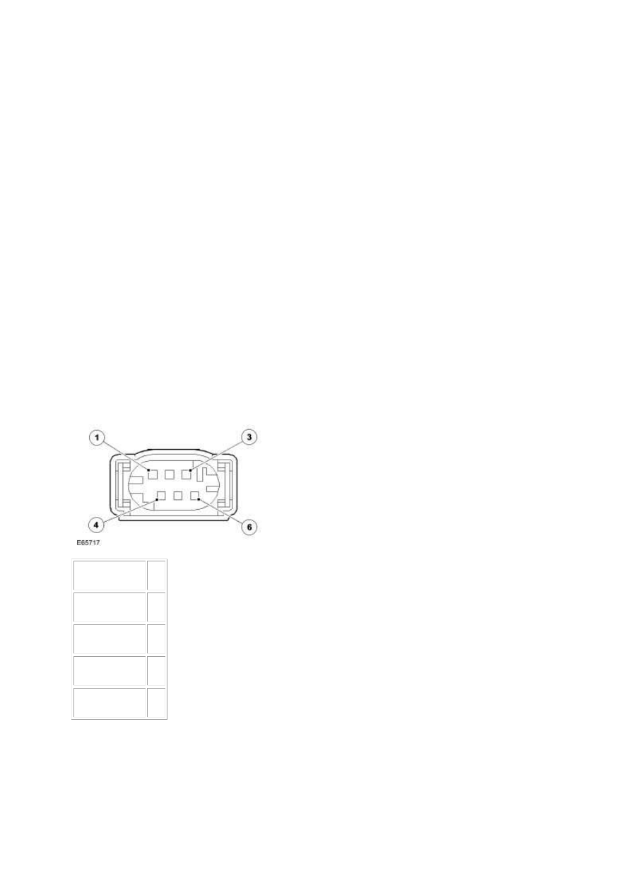
1.
Circuit
Pin
CAN negative
01
CAN positive
02
Sensor power
03
Sensor ground 05

2.
Circuit
Pin
CAN negative
19
CAN positive
18
Sensor power
22
Sensor ground 29
3. Key off. 4. Disconnect the yaw rate sensor and accelerometer connector, IP023 5. Key on, engine
off. 6. Measure the resistance between:
IP023, harness side
Battery
Pin 03
Negative terminal
•
Is the voltage greater than 4 volts?
-> Yes
GO to Pinpoint Test
G531322t64
.
-> No
GO to Pinpoint Test
G531322t62
.
G531322t62 : CHECK THE YAW RATE SENSOR AND ACCELEROMETER
POWER SUPPLY CIRCUIT FOR SHORT CIRCUIT TO GROUND
1. Measure the resistance between:
IP023, harness side
Battery
www.

Pin 03
Negative terminal
•
Is the resistance greater than 10 Kohms?
-> Yes
GO to Pinpoint Test
G531322t63
.
-> No
REPAIR the short circuit. For additional information, refer to the wiring diagrams. Clear the DTC, test
the system for normal operation by driving the vehicle to a speed greater than 20 Kph (12.5 mph) for
more than 3 seconds.
G531322t63 : CHECK THE YAW RATE SENSOR AND ACCELEROMETER
POWER SUPPLY CIRCUIT FOR HIGH RESISTANCE
1. Key off. 2. Disconnect the ABS module connector, EC030. 3. Measure the resistance between:
IP023, harness side EC030, harness side
Pin 03
Pin 22
•
Is the resistance less than 10 ohms?
-> Yes
An intermittent fault may be present in the wiring harness. Visually check for chaffed wires or other
physical damage to the harness.
-> No
REPAIR the high resistance circuit. For additional information, refer to the wiring diagrams. Clear the
DTC, test the system for normal operation by driving the vehicle to a speed greater than 20 Kph (12.5
mph) for more than 3 seconds.
G531322t64 : CHECK THE GROUND CIRCUIT TO THE YAW RATE SENSOR
AND ACCELEROMETER
1. Measure the resistance between:
IP023, harness side
Battery
Pin 05
Negative terminal

•
Is the resistance less than 10 ohms?
-> Yes
GO to Pinpoint Test
G531322t68
.
-> No
GO to Pinpoint Test
G531322t65
.
G531322t65 : CHECK THE YAW RATE SENSOR AND ACCELEROMETER
GROUND CIRCUIT FOR SHORT CIRCUIT TO POWER
1. Measure the resistance between:
IP023, harness side
Battery
Pin 05
Positive terminal
•
Is the resistance greater than 10 Kohms?
-> Yes
GO to Pinpoint Test
G531322t67
.
-> No
GO to Pinpoint Test
G531322t66
.
G531322t66 : CHECK WHETHER THE SHORT CIRCUIT IS IN THE HARNESS
OR THE MODULE
1. Key off. 2. Disconnect the ABS module connector, EC030. 3. Key on, engine off. 4. Measure the
resistance between:
IP023, harness side
Battery
Pin 05
Positive terminal
•
Is the resistance greater than 10 Kohms?
-> Yes
Refer to the warranty policy and procedures manual if a module is suspect.
www.
Нет комментариевНе стесняйтесь поделиться с нами вашим ценным мнением.
Текст