Jaguar XJ (X350). Manual — part 869

Is the resistance greater than 5 ohms?
-> Yes
REPAIR the high resistance circuit. For additional information, refer to the wiring diagrams. CLEAR the
DTC and test the system for normal operation.
-> No
GO to Pinpoint Test G531330t56.
G531330t56 : CHECK KS GROUND CIRCUIT FOR HIGH RESISTANCE
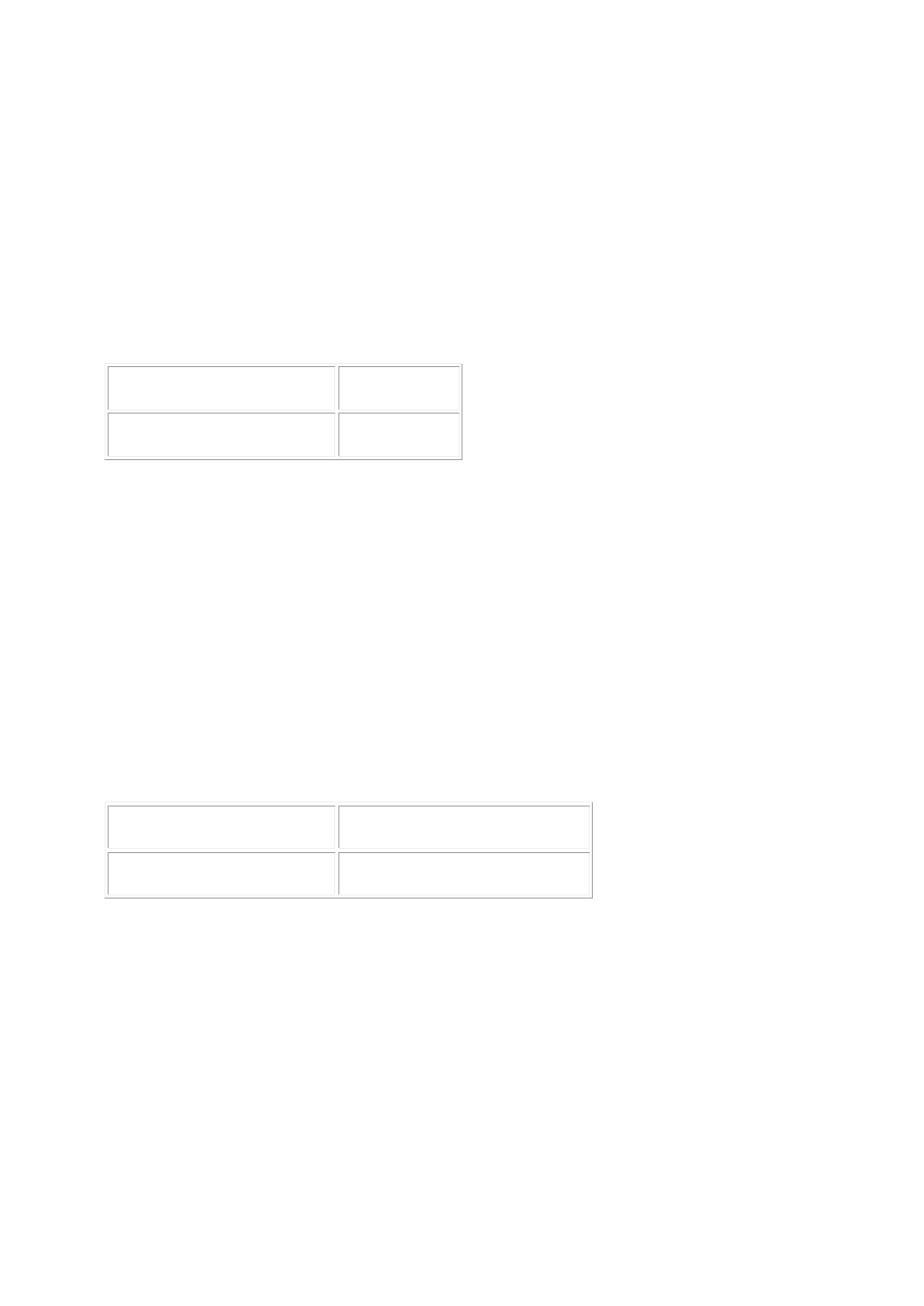
1. Measure the resistance between:
KS connector PI60, harness side ECM connector PI300, harness side
Pin 02
Pin 19
Is the resistance greater than 5 ohms?
-> Yes
REPAIR the high resistance circuit. For additional information, refer to the wiring diagrams. CLEAR the
DTC and test the system for normal operation.
-> No
INSTALL a new KS.
Knock Sensor (KS) RH (18.30.93) CLEAR the DTC and test the system for normal operation.
PINPOINT TEST G531330p16 : LEFT-
HAND KNOCK SENSOR (KS) CIRCUIT
G531330t59 : CHECK KS SENSING CIRCUIT FOR SHORT CIRCUIT TO GROUND
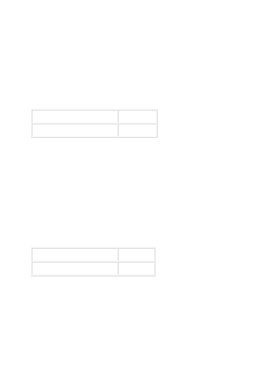
1. Disconnect the KS electrical connector, PI61. 2. Measure the resistance between:
KS connector PI61, harness side
Battery
Pin 01
Negative terminal
Is the resistance less than 10,000 ohms?
-> Yes
REPAIR the short circuit. For additional information, refer to the wiring diagrams. CLEAR the DTC and
test the system for normal operation.
-> No
GO to Pinpoint Test G531330t58.
G531330t58 : CHECK KS SENSING CIRCUIT FOR SHORT CIRCUIT TO POWER
1. Measure the resistance between:
KS connector PI61, harness side
Battery
Pin 01
Positive terminal
Is the resistance less than 10,000 ohms?
-> Yes
REPAIR the short circuit. For additional information, refer to the wiring diagrams. CLEAR the DTC and
test the system for normal operation.
-> No
GO to Pinpoint Test G531330t57.
G531330t57 : CHECK KS SENSING CIRCUIT FOR HIGH RESISTANCE
1. Disconnect the ECM electrical connector, PI300. 2. Measure the resistance between:
KS connector PI61, harness side ECM connector PI300, harness side
Pin 01
Pin 43
Is the resistance greater than 5 ohms?
-> Yes
REPAIR the high resistance circuit. For additional information, refer to the wiring diagrams. CLEAR the
DTC and test the system for normal operation.
-> No
GO to Pinpoint Test G531330t60.
www.

G531330t60 : CHECK KS GROUND CIRCUIT FOR HIGH RESISTANCE
1. Measure the resistance between:
KS connector PI61, harness side ECM connector PI300, harness side
Pin 02
Pin 20
Is the resistance greater than 5 ohms?
-> Yes
REPAIR the high resistance circuit. For additional information, refer to the wiring diagrams. CLEAR the
DTC and test the system for normal operation.
-> No
INSTALL a new KS.
Knock Sensor (KS) LH (18.30.92) CLEAR the DTC and test the system for normal operation.
PINPOINT TEST G531330p17 :
CRANKSHAFT POSITION (CKP)
SENSOR CIRCUIT
G531330t61 : CHECK THE CKP SENSOR FOR CORRECT INSTALLATION
1. Check the CKP sensor for correct installation.
Is the CKP sensor correctly installed?
-> Yes
GO to Pinpoint Test G531330t62.
-> No
INSTALL the CKP sensor correctly.
Crankshaft Position (CKP) Sensor (18.30.12) Reconnect the sensor. CLEAR the DTCs and test the
system for normal operation.
G531330t62 : CHECK THE CKP SENSOR FOR DEBRIS
1. Remove the CKP sensor and inspect for debris.
Is the CKP sensor free of debris?
-> Yes
GO to Pinpoint Test G531330t65.
-> No
CLEAN the sensor and wheel. INSTALL the sensor.
Crankshaft Position (CKP) Sensor (18.30.12) Reconnect the sensor. CLEAR the DTCs and test the
system for normal operation.
G531330t65 : CHECK THE CKP SENSOR SENSING CIRCUIT FOR SHORT
CIRCUIT TO GROUND
1. Disconnect the CKP sensor electrical connector, PI21. 2. Measure the resistance between:
CKP sensor connector PI21, harness side
Battery
Pin 02
Negative terminal
Is the resistance less than 10,000 ohms?
-> Yes
REPAIR the short circuit. For additional information, refer to the wiring diagrams. CLEAR the DTC and
test the system for normal operation.
-> No
GO to Pinpoint Test G531330t64.
G531330t64 : CHECK THE CKP SENSOR SENSING CIRCUIT FOR SHORT
CIRCUIT TO POWER
1. Measure the resistance between:
CKP sensor connector PI21, harness side
Battery
Pin 02
Positive terminal
Is the resistance less than 10,000 ohms?
-> Yes
REPAIR the short circuit. For additional information, refer to the wiring diagrams. CLEAR the DTC and
test the system for normal operation.
-> No
GO to Pinpoint Test G531330t63.
www.
Нет комментариевНе стесняйтесь поделиться с нами вашим ценным мнением.
Текст