Jaguar XJ (X350). Manual — part 865

-> Yes
REPAIR the short circuit. For additional information, refer to the wiring diagrams. CLEAR the DTC and
test the system for normal operation.
-> No
GO to Pinpoint Test G531330t24.
G531330t24 : CHECK H02S HEATER CONTROL CIRCUIT FROM ECM FOR
HIGH RESISTANCE
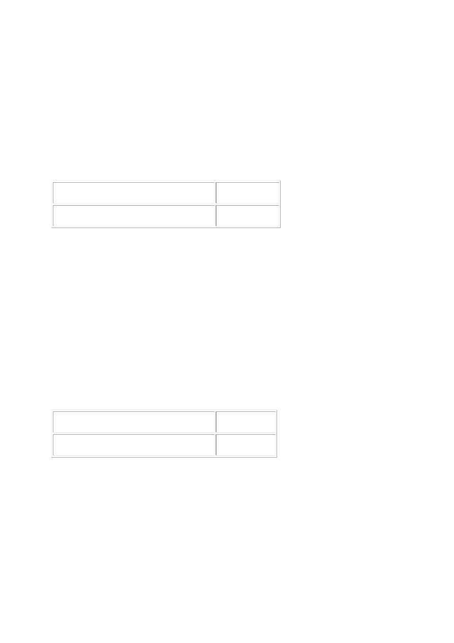
1. Disconnect the ECM electrical connector, PI300. 2. Measure the resistance between:
H02S connector PI10, harness side ECM connector PI300, harness side
Pin 02
Pin 76
Is the resistance greater than 5 ohms?
-> Yes
REPAIR the high resistance circuit. For additional information, refer to the wiring diagrams. CLEAR the
DTC and test the system for normal operation.
-> No
INSTALL a new H02S.
Heated Oxygen Sensor (HO2S) CLEAR the DTC and test the system for normal operation.
PINPOINT TEST G531330p8 : RIGHT-
HAND CATALYST MONITOR SENSOR
SENSING AND GROUND CIRCUITS
G531330t29 : CHECK THE CATALYST MONITOR SENSOR SENSING CIRCUIT
FOR SHORT CIRCUIT TO GROUND
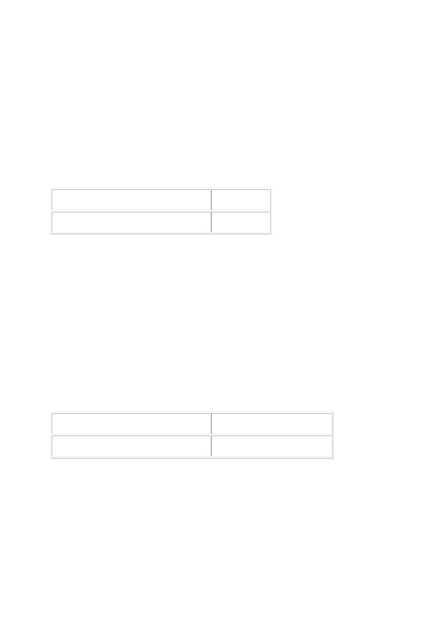
1. Disconnect the catalyst monitor electrical connector, PI11. 2. Measure the resistance between:
Catalyst monitor connector PI11, harness side
Battery
Pin 04
Negative terminal
Is the resistance less than 10,000 ohms?
-> Yes
REPAIR the short circuit. For additional information, refer to the wiring diagrams. CLEAR the DTC and
test the system for normal operation.
-> No
GO to Pinpoint Test G531330t28.
G531330t28 : CHECK THE CATALYST MONITOR SENSOR SENSING CIRCUIT
FOR SHORT CIRCUIT TO POWER
1. Measure the resistance between:
Catalyst monitor connector PI11, harness side
Battery
Pin 04
Positive terminal
Is the resistance less than 10,000 ohms?
-> Yes
REPAIR the short circuit. For additional information, refer to the wiring diagrams. CLEAR the DTC and
test the system for normal operation.
-> No
GO to Pinpoint Test G531330t27.
G531330t27 : CHECK THE CATALYST MONITOR SENSOR SENSING CIRCUIT
FOR HIGH RESISTANCE
1. Disconnect the ECM electrical connector, PI300. 2. Measure the resistance between:
Catalyst monitor connector PI11, harness side ECM connector PI300, harness side
Pin 04
Pin 40
Is the resistance greater than 5 ohms?
-> Yes
REPAIR the high resistance circuit. For additional information, refer to the wiring diagrams. CLEAR the
DTC and test the system for normal operation.
-> No
www.

GO to Pinpoint Test G531330t30.
G531330t30 : CHECK THE CATALYST MONITOR SENSOR GROUND CIRCUIT
FOR HIGH RESISTANCE
1. Measure the resistance between:
Catalyst monitor connector PI11, harness side ECM connector PI300, harness side
Pin 03
Pin 22
Is the resistance greater than 5 ohms?
-> Yes
REPAIR the high resistance circuit. For additional information, refer to the wiring diagrams. CLEAR the
DTC and test the system for normal operation.
-> No
INSTALL a new catalyst monitor sensor.
Catalyst Monitor Sensor (18.30.66) CLEAR the DTC and test the system for normal operation.
PINPOINT TEST G531330p9 : RIGHT-
HAND CATALYST MONITOR SENSOR
SUPPLY AND HEATER CONTROL
CIRCUITS
G531330t31 : CHECK THE CATALYST MONITOR HEATER POWER SUPPLY
CIRCUIT
1. Disconnect the catalyst monitor sensor electrical connector, PI11. 2. Key on, engine off. 3. Make
sure the O2S heater relay is energized. 4. Measure the voltage between:
Catalyst monitor connector PI11, harness side
Battery
Pin 01
Negative terminal
Is the voltage greater than 10 volts?
-> Yes
GO to Pinpoint Test G531330t170.
-> No
REPAIR the power supply circuit to the catalyst monitor heater. This circuit includes the O2S heater
relay and fuse 33 of the front power distribution box. For additional information, refer to the wiring
diagrams. CLEAR the DTC and test the system for normal operation.
G531330t170 : CHECK THE CATALYST MONITOR HEATER CONTROL
CIRCUIT FOR SHORT CIRCUIT TO GROUND
1. Key off. 2. Measure the resistance between:
Catalyst monitor connector PI11, harness side
Battery
Pin 02
Negative terminal
Is the resistance less than 10,000 ohms?
-> Yes
REPAIR the short circuit. For additional information, refer to the wiring diagrams. CLEAR the DTC and
test the system for normal operation.
-> No
GO to Pinpoint Test G531330t171.
G531330t171 : CHECK THE CATALYST MONITOR HEATER CONTROL
CIRCUIT FOR SHORT CIRCUIT TO POWER
1. Measure the resistance between:
Catalyst monitor connector PI11, harness side
Battery
Pin 02
Positive terminal
Is the resistance less than 10,000 ohms?
-> Yes
REPAIR the short circuit. For additional information, refer to the wiring diagrams. CLEAR the DTC and
test the system for normal operation.
-> No
GO to Pinpoint Test G531330t32.
www.
Нет комментариевНе стесняйтесь поделиться с нами вашим ценным мнением.
Текст