Jaguar XJ (X350). Manual — part 89
The system comprises a TPMS module, a RF antenna, 4 initiators and 4 or 5 tire pressure sensors,
depending on the type of spare wheel fitted.
The TPMS module is located on the LH (left-hand) side of the trunk. The RF antenna is located
beneath the rear of the vehicle. The front initiators are positioned at the front of the wheel arches,
behind the fender splash shields. The rear initiators are positioned at the rear of the rear wheel
arches, behind the fender splash shields.
The 4 initiators are hardwired to the TPMS module. The initiators transmit 125 KHz Low Frequency
(LF) signals to the tire pressure sensors which respond by modifying the mode status within the RF
transmission. The 315 or 433 MHz RF signals are detected by the RF antenna which is connected
directly to the TPMS module. The received RF signals from the tire pressure sensors are passed to the
TPMS module and contain identification, pressure, temperature and acceleration information for
each wheel and tire.
The TPMS module communicates with the instrument cluster via the high speed CAN (controller area
network) bus to provide the driver with appropriate warnings. The TPMS module also indicates
status or failure of the TPMS or components.
Tire Location and Identification
The TPMS can identify the position of the wheels on the vehicle and assign a received tire pressure
sensor identification to a specific position on the vehicle, for example FL (front left), FR (front right),
RL (rear left) and RR (rear right). This feature is required because of the different pressure targets
and threshold between the front and rear tires.
The wheel location is performed automatically by the TPMS module using an 'auto-location' function.
This function is fully automatic and requires no input from the driver. The TPMS module
automatically re-learns the position of the wheels on the vehicle if the tire pressure sensors are
replaced or the wheel positions on the vehicle are changed.
The TPMS software can automatically detect, under all operating conditions, the following:
•
one or more new tire pressure sensors have been fitted
•
one or more tire pressure sensors have stopped transmitting
•
reject identifications from tire pressure sensors which do not belong to the vehicle
•
two 'running' wheels on the vehicle have changed positions.
If a new tire pressure sensor is fitted on any 'running' wheel, the module can learn the new sensor
identification automatically when the vehicle is driven for more than 15 minutes at a speed of more
than 20 km/h (12.5 mph).
The tire learn and location process is ready to commence when the vehicle has been stationary or
traveling at less than 12 mph (20 km/h) for 15 minutes. This is known as 'parking mode'. The
learn/locate process requires the vehicle to be driven at speeds of more than 20 km/h (12.5 mph) for
15 minutes. If the vehicle speed reduces to below 20 km/h (12.5 mph), the learn process timer is
suspended until the vehicle speed increases to more than 20 km/h (12.5 mph), after which time the

timer is resumed. If the vehicle speed remains below 20 km/h (12.5 mph) for more than 15 minutes,
the timer is set to zero and process starts again.
If the tire pressure sensors fitted to the running wheels vehicle are changed, the module can learn
the new sensor identifications automatically. The learn function requires no manual intervention by
the driver.
INITIATOR
The front initiators are located near the front of the front wheel arches, behind the fender splash
shields. The rear initiators are located at the rear of the rear wheel arches, behind the fender splash
shields. Each initiator has a connector which connects to the vehicle body harness.
The initiator is a passive LF transmitter. It transmits signals which are received by the tire pressure
sensors prompting them to modify their mode status.
The TPMS module energizes each initiator in turn using LF drivers. The corresponding tire pressure
sensor detects the LF signal and responds by modifying the mode status within the RF transmission.
TIRE PRESSURE SENSOR
www.
The TPMS uses active tire pressure sensors which are located on each wheel, inside the tire cavity.
The sensor incorporates the tire valve and is secured by a nut on the outside of the wheel. The
sensor contains a Printed Circuit Board (PCB) which houses a PTC (positive temperature coefficient)
sensor, a Piezo pressure sensor, a radio receiver and transmitter and a lithium battery.
The tire pressure sensors use the PTC (positive temperature coefficient) sensor and the Piezo sensor
to periodically measure the pressure and temperature of the air inside the tire. The data is
transmitted by RF data signals at either 315 MHz or 433 MHz dependant on market requirements.
The RF transmission from the sensor contains a unique identification code in its transmission data.
This allows the TPMS to identify the wheel on the vehicle. The tire pressure sensor can also detect
when the wheel is rotating. In order to preserve battery power, the sensor uses different
transmission rates when the wheel is stationary or moving.
If a sensor is replaced on a 'running wheel', the vehicle must remain stationary for 15 minutes before
being driven. This allows the system to detect the new sensor. To initiate full TPMS operation, the
vehicle must then be driven at a speed of more than 20 km/h (12.5 mph) for 15 minutes, then remain
stationary for a further 15 minutes.
Care Points
The care points detailed in 'Tire Changing' earlier in this section must be followed to avoid damage to
the sensor.
If a new sensor or tire is fitted, a new nut, seal and washer must also be fitted and the sensor nut
tightened to the correct torque as given in the Removal and Installation section of this manual.
If the valve nut is loosened, the seal, washer and nut must be replaced.
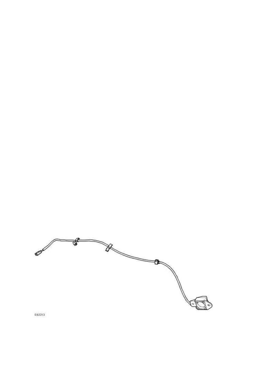
RF ANTENNA
The TPMS RF antenna is located at the rear of the vehicle and is mounted between the spare wheel
well and rear subframe. The unit receives tire pressure, temperature and acceleration readings from
each tire and interfaces with the TPMS module. The TPMS module then transmits the appropriate

messages to the instrument cluster. The unit also receives further information from each tire
pressure sensor concerning wheel identification, mode status and the condition of the tire pressure
sensor battery.
INSTRUMENT CLUSTER AND MESSAGE CENTER
Item
Part Number
Description
1
Low tire pressure warning indicator
2
Message Center
The warning indications to the driver are common on all vehicles fitted with TPMS. The driver is
alerted to system warnings by a low tire pressure warning indicator in the instrument cluster and an
applicable text message in the message center.
The TPMS module passes system status information to the instrument cluster on the high speed CAN
(controller area network) bus. The instrument cluster then converts this data into illumination of the
warning indicator and display of an appropriate message.
When the ignition is switched on, the warning indicator is illuminated for 3 seconds for a bulb check.
NOTE:
If the vehicle is not fitted with the TPMS, the warning indicator will not illuminate.
The instrument cluster checks, within the 3 second bulb check period, for a CAN (controller area
network) bus message from the TPMS. During this time the TPMS performs internal tests and CAN
(controller area network) bus initialization. The warning indicator will be extinguished if the TPMS
module does not issue a fault message or tire pressure warning message.
If a TPMS fault warning message is detected by the instrument cluster at ignition on, the warning
www.
Нет комментариевНе стесняйтесь поделиться с нами вашим ценным мнением.
Текст