Jaguar XJ (X350). Manual — part 956

-> Yes
REPAIR the short circuit. For additional information, refer to the wiring diagrams. CLEAR the DTC, test
the system for normal operation.
-> No
GO to Pinpoint Test G531332t109.
G531332t109 : CHECK THE BRAKE SWITCH SIGNAL CIRCUIT FOR SHORT
CIRCUIT TO POWER
1. Measure the resistance between:
Brake switch connector CR78, harness side
Battery
Pin 02
Positive terminal
Is the resistance less than 10,000 ohms?
-> Yes
REPAIR the short circuit. For additional information, refer to the wiring diagrams. CLEAR the DTC, test
the system for normal operation.
-> No
GO to Pinpoint Test G531332t110.
G531332t110 : CHECK THE BRAKE SWITCH SIGNAL CIRCUIT FOR HIGH
RESISTANCE
1. Disconnect the ECM electrical connector, EC300. 2. Measure the resistance between:
Brake switch connector CR78, harness side ECM connector EC300, harness side
Pin 02
Pin 41
Is the resistance greater than 5 ohms?
-> Yes
REPAIR the high resistance circuit. For additional information, refer to the wiring diagrams. CLEAR the
DTC, test the system for normal operation.
-> No
REFER to the warranty policy and procedures manual if an ECM is suspect.
Removal and installation
Brake Pedal Position (BPP) Switch
Removal
1 . Switch the ignition on.
2 . Position the front seat fully rearwards.
3 . Switch the ignition off.
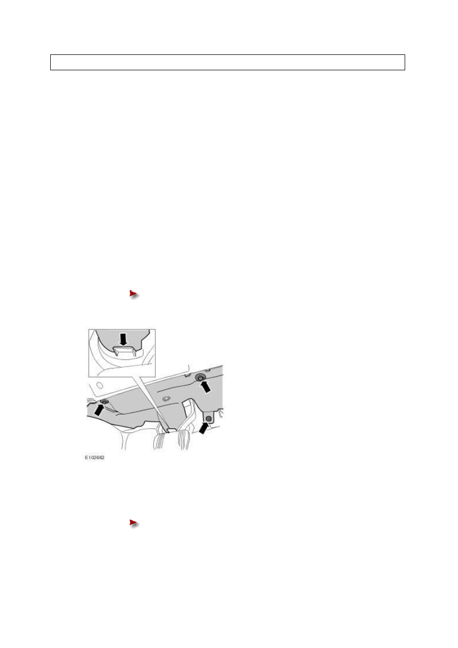
4 . Remove the driver's side footwell trim panel.
Release the 3 clips.
5 . Release the brake pedal position (BPP) switch.
Rotate the BPP switch 45 degrees counter-clockwise.
www.
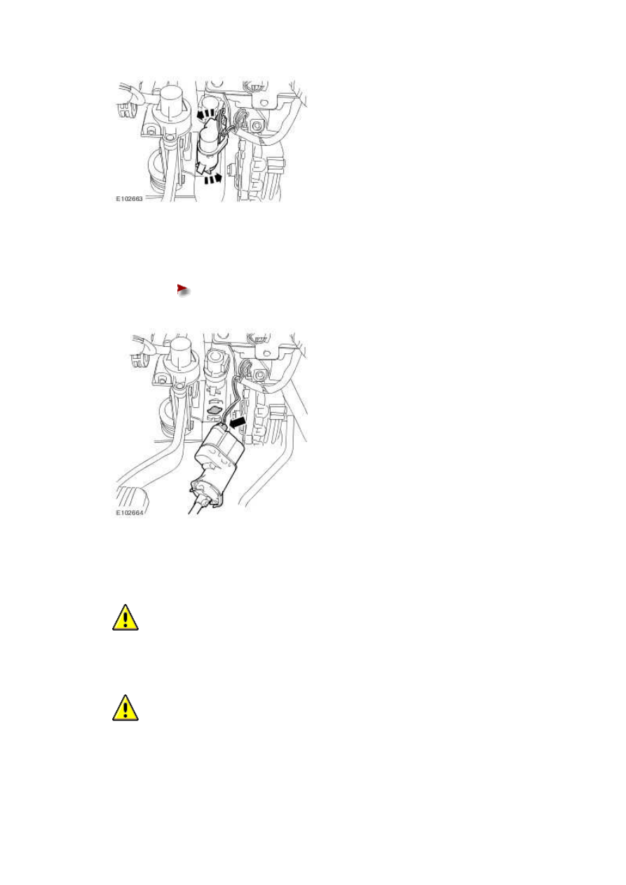
6 . Remove the BPP switch.
Disconnect the electrical connector.
Installation
1
.
CAUTION: Make sure that the brake pedal remains in the rest position during this
procedure.
CAUTION: The bracket is keyed to avoid incorrect orientation. Failure to correctly
align the switch may result in damage to the vehicle.

CAUTION: Make sure that the pedal box, booster-to-brake pedal assembly and
switch bracket are all installed correctly before installing the switch.
Install the BPP switch.
Locate the BPP switch in the bracket.
Rotate the BPP switch 45 degrees clockwise.
2 . Connect the electrical connector.
3 . Install the driver's side footwell trim panel.
Align the trim panel with the guide.
Install the 3 clips.
www.
Нет комментариевНе стесняйтесь поделиться с нами вашим ценным мнением.
Текст