Jaguar XJ (X350). Manual — part 1265
Beltminder
European Beltminder
The beltminder function is an additional warning to the safety belt reminder. Under the conditions
where a front seat occupant is unbelted or becomes unbelted and the vehicle is moving above 16
km/h (10 mile/h) then an additional audible warning of an intermittent tone will start accompanied
by the safety belt warning lamp flashing. The intermittent audible warning and flashing lamp will last
for 10 seconds and will repeat every 30 seconds for five minutes. The additional warnings will stop
when all occupants seated in the front of the vehicle have their safety belts fastened or if the vehicle
speed drops below 5 km/h (3 mile/h).
North American Beltminder
The system will function the same as for European beltminder after 75 seconds.
Beltminder Disabling
This process is common to both European and North American beltminder.
1 . Make sure the front passenger seat is unoccupied.
NOTE:
Steps two to five must be completed within 60 seconds.
2 . Turn the ignition lock cylinder to the ON position (do not start the engine).
3 . Buckle the driver safety belt buckle and wait until the safety belt warning lamp extinguishes.
4 . Unbuckle the driver safety belt buckle and wait until the safety belt warning lamp illuminates.
5 . Repeat Steps three and four a further eight times.
6 . When the driver safety belt buckle is unbuckled for the ninth time a single audible warning will
sound. The single audible warning is acknowledgment that the beltminder feature has been disabled.
The beltminder feature will be disabled until the above process (steps one to six) are repeated. Upon
repeating the process the beltminder feature will be reactivated.
Air Bag Inactive Warning
If a fault is present in the supplementary restraints system and the warning lamp in the instrument
cluster is inoperative, then the restraints control module will send a signal to the instrument cluster
to activate an audible warning. The audible warning will not sound for the first 90 seconds when the
ignition lock cylinder is in the ON position . The audible warning will then sound continuously for 5
seconds and stay silent for 5 seconds, this sequence repeats 5 times and the function will repeat
every 30 minutes until the fault has been rectified.

Parking Brake Warning
Operation of the parking brake when the vehicle is in motion will cause the message 'PARKBRAKE
ON' to be displayed in the message center, the warning lamp in the instrument cluster will be
displayed and an audible warning will sound.
Parking Aid
CAUTION: It is the drivers responsibility to check for any obstacles and judge the vehicles
distance from them. Overhanging objects, barriers, thin obstructions or painted surfaces may not
be detected by the vehicles parking aid. Failure to follow this instruction may result in damage to
the vehicle.
NOTE:
Front parking aid will also operate when reverse gear is selected.
Parking aid provides an audible proximity warning when parking. If an obstacle is detected at the
front or rear of the vehicle, an audible warning will sound from the front or rear speakers
respectively, the audible warning will increase in speed as the vehicle approaches the obstacle. The
front and rear parking aid audible warning will become continuous when an object is detected at or
within 300 mm (12 inch) from the rear of the vehicle or approximately 250 mm (10 inch) from the
front of the vehicle. If the parking aid has a fault when engaging reverse gear or switching the
ignition lock cylinder to the ON position, a single 3 second audible warning will sound. Parking aid will
be automatically disabled as soon as a fault is detected.
Adaptive Cruise Control (ACC)
WARNING: It is the drivers responsibility to slow the vehicle down when the 'DRIVER
INTERVENE' message is displayed in the message center. Failure to follow this instruction may
result in personal injury.
CAUTION: It is the drivers responsibility to slow the vehicle down when the 'DRIVER
INTERVENE' message is displayed in the message center. Failure to follow this instruction may
result in damage to the vehicle.
If adaptive cruise control (ACC) is active, an amber warning light is illuminated to indicate that the
vehicle is in 'FOLLOW MODE' and is automatically maintaining the set distance from the vehicle
immediately ahead. Maximum braking which is applied to the ACC system is limited and can be
overridden by the driver applying the brakes. If the ACC system predicts that it's maximum braking
level will not be sufficient, an audible warning will sound and the message 'DRIVER INTERVENE' will
www.

be displayed in the message center. If the vehicle speed decreases below 30 km/h (18 mile/h), the
ACC system will be automatically switched off and the instrument warning light will go out. If the
brakes have been applied by the ACC system, they will be slowly released, this will be accompanied
by an audible warning, the message 'DRIVER INTERVENE' will again be displayed in the message
center.
Adaptive Cruise Control (ACC) Failure
WARNING: It is the drivers responsibility to slow the vehicle down when the 'DRIVER
INTERVENE' message is displayed in the message center. Failure to follow this instruction may
result in personal injury.
CAUTION: It is the drivers responsibility to slow the vehicle down when the 'DRIVER
INTERVENE' message is displayed in the message center. Failure to follow this instruction may
result in damage to the vehicle.
If a fault occurs during the operation of the ACC system in 'CRUISE' or 'FOLLOW' modes, the ACC
system will switch off and cannot be used until the fault is cleared. The message 'DRIVER INTERVENE'
will be displayed briefly in the message center followed by the message 'CRUISE NOT AVAILABLE'. If
failure of the ACC or any related system occurs at any other time the message 'CRUISE NOT
AVAILABLE' will be displayed and it will not be possible to active the ACC system. Accumulated
debris, dirt, snow or ice on the ACC sensor or it's cover may inhibit the ACC operation. Fitting of a
vehicle front protector or metallized badges may also affect ACC operation. If this occurs and audible
warning will sound and the message 'DRIVER INTERVENE' will be briefly displayed in the message
center followed by the message 'ACC SENSOR BLOCKED'. This will render the ACC system inactive.
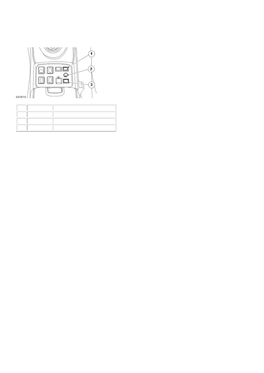
Warning Devices – Armoured
Item Part Number
Description
1
Intercom switch ON/OFF
2
Intercom switch INSIDE/OUTSIDE
3
Potentiometer
Intercom
In order to activate the intercom system, press the green switch. Communication is as follows: To speak
from the inside of the vehicle to the outside of the vehicle press the yellow switch whilst speaking. Release
the yellow switch to make the outside listening permanent. If you want to increase the interior volume of the
loud speaker, turn the potentiometer clock wise. The amplifier is located in the rear luggage area inside the
‘options box’. The microphone inside of the vehicle is located near to the driver. The microphone outside of
the vehicle is located near to the rear view door mirror. The outside loudspeaker is located under the front of
the bumper cover. The inside loudspeaker is located under the instrument panel.
Siren
The siren system consists of a luggage compartment amplifier and two relays, a floor console mounted
switch, and a speaker mounted behind the front bumper cover on the left hand side of the vehicle. The siren
system is integrated into the vehicle with a harness kit part number 6W9M-12B654-BA. The electrical feed
is via fuse number 5 in the luggage compartment mounted auxiliary fuse box. An electrical feed from the
battery positive terminal is supplied on a red wire to the auxiliary junction box mounted in the luggage
compartment of the vehicle. Fuse 5 provides a feed to the power relay on a PY wire. The siren 'arm' signal
(XS007-6) is taken to the relay siren XS006-30 on a G wire. The arm signal is grounded at the amplifier
XS007-4 on a B wire via the relay siren. When the siren switch (XS005) is activated an ignition feed is
provided to the power relay coil (XS002-85) on a WB wire, and to the relay siren (XS006-85) on a WB
wire. The coils are earthed on B wires. The power relay (XS002) is pulled in connecting a feed to the siren
amplifier XS010-1 on a RY wire. The amplifier ground connection (XS010-2) is taken to XS012-1 via a B
wire. At the same time, the relay siren (XS006) is pulled in, and the siren 'arm' signal has its path to ground
removed. The siren is now 'armed' and under the control of the vehicle horn switch. When the vehicle horn
switch is pushed the siren starts in wail mode. A further push toggles the siren into yelp mode. Two pushes
in quick succession will cancel the siren, as will returning the siren switch to the off position. The toggle
function is enabled via the vehicle horn circuit connected to the amplifier XS007-15 on an YB wire. The
siren speaker (XS008 and XS009) is connected to the amplifier XS007 via an N and NW wire. A feed for
the switch illumination is provided on a RW wire, and is grounded via a B wire at XI001.
Published: Mar 12, 2014
Vehicles
www.
Нет комментариевНе стесняйтесь поделиться с нами вашим ценным мнением.
Текст