Jaguar XJ (X350). Manual — part 1072
-> No
Repair the electrical circuit between the J-gate assembly electrical connector CA245 Pin 1 (GO) and
the rear power distribution box FUSE 3. Clear the DTC. TEST the system for normal operation. NOTE:
This circuit incorporates the ignition switch and the primary junction box. For additional information,
refer to the vehicle wiring diagrams.
G189073t6 : CHECK THE GROUND SUPPLY TO THE J-GATE
1. Measure the resistance between the J-gate assembly electrical connector CA245 Pin 2 (B) and
GROUND.
Is the resistance less than 5.0 Ohms?
-> Yes
GO to Pinpoint Test G189073t2.
-> No
Repair the circuit between the J-gate assembly electrical connector CA245 Pin 2 (B) and GROUND.
Clear the DTC. TEST the system for normal operation.
G189073t2 : CHECK FOR J-GATE ILLUMINATION FEED
1. Turn the ignition to the "ON" position. 2. Measure the voltage at CA245 Pin 3 (UY).
Is the voltage greater than 10 Volts?
-> Yes
GO to Pinpoint Test G189073t3.
-> No
Repair the electrical circuit between the J-gate assembly electrical connector CA245 Pin 3 (UY) and
the front electronics module electrical connector. For additional information, refer to the vehicle
wiring diagrams. Clear the DTC. TEST the system for normal operation.
G189073t3 : CHECK FOR KEY INTERLOCK FEED CIRCUIT FOR CONTINUITY
1. Disconnect the J-gate assembly electrical connector CA245. 2. Disconnect the ignition switch
electrical connector FC018. 3. 3) Measure the resistance between the J-gate assembly electrical
connector CA245 Pin 4 (Y) and the ignition switch electrical connector FC018 Pin 3 (Y).
Is the resistance less than 5.0 Ohms?
-> Yes
GO to Pinpoint Test G189073t4.
-> No
Repair the electrical circuit between the J-gate assembly electrical connector CA245 Pin 4 (Y) and the
ignition switch electrical connector FC018 Pin 3 (Y). Clear the DTC. TEST the system for normal
operation.
G189073t4 : CHECK FOR KEY INTERLOCK ACTION
1. Check for continuity between Pin 3 and Pin 4 of the ignition switch lock cylinder.
Is the circuit continuous?
-> Yes
Install a new J-gate. For additional information,
Clear the DTC. TEST the system for normal operation.
-> No
Install a new ignition switch lock cylinder. For additional information, <<211-04>> Clear the DTC. TEST
the system for normal operation.
www.
Removal and installation
Selector Lever Cable and Bracket
(44.15.08)
Removal
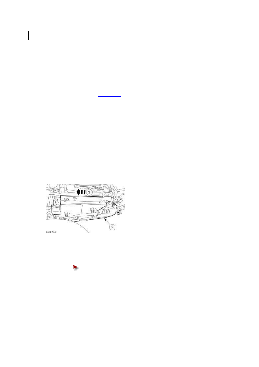
1 . Remove the floor console. <<501-12>>
2 . Move the transmission selector lever to the "R" position.
3 . Detach the wiring harness bracket.
1) Reposition the wiring harness.
2) Detach the wiring harness bracket.
4 . Detach the selector lever cable.
Loosen the selector lever cable retaining nuts.
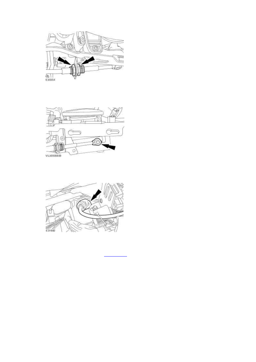
5 . Detach the selector lever cable.
6 . Detach the selector lever cable.
7 . Raise and support the vehicle. <<100-02>>
8 . Detach the selector lever cable.
www.
Нет комментариевНе стесняйтесь поделиться с нами вашим ценным мнением.
Текст