Jaguar XJ (X350). Manual — part 1438
Item Part Number
Description
1
Front seat head restraint motor
2
Front lumbar motor
3
Front seat recline motor
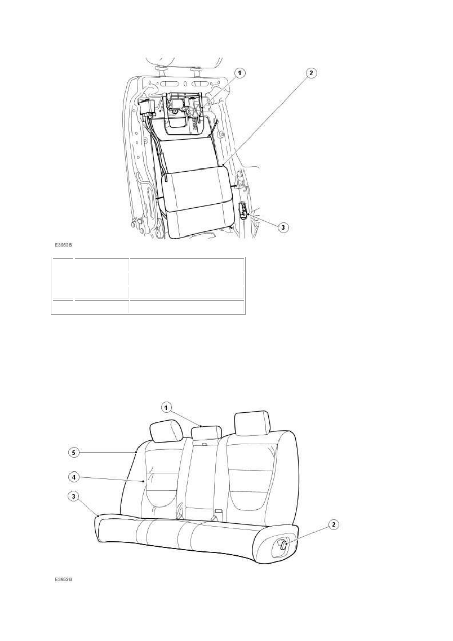
REAR SEATS
Rear Seats
Front Seat Backrest Motors
Item Part Number
Description
1
Seat armrest
2
Rear seat control switch
3
Rear seat cushion
4
Rear outer seat backrest
5
Rear seat head restraint
Depending on the vehicle specification the rear seats will be one of the following:
•
Fixed bench style with an integral armrest.
•
Electrically adjustable outer seat backrests with a bench style cushion and separate
armrest.
•
Electrically adjustable twin rear seats with a full floor console.
The standard rear seat is of a bench type with full width removable cushion and integral
armrest.
The electrically adjustable outer seat backrests can be fitted with either a bench style cushion
that incorporates both the rear seat control switches or single rear seat cushions that
incorporate the rear seat control switch for the corresponding side.
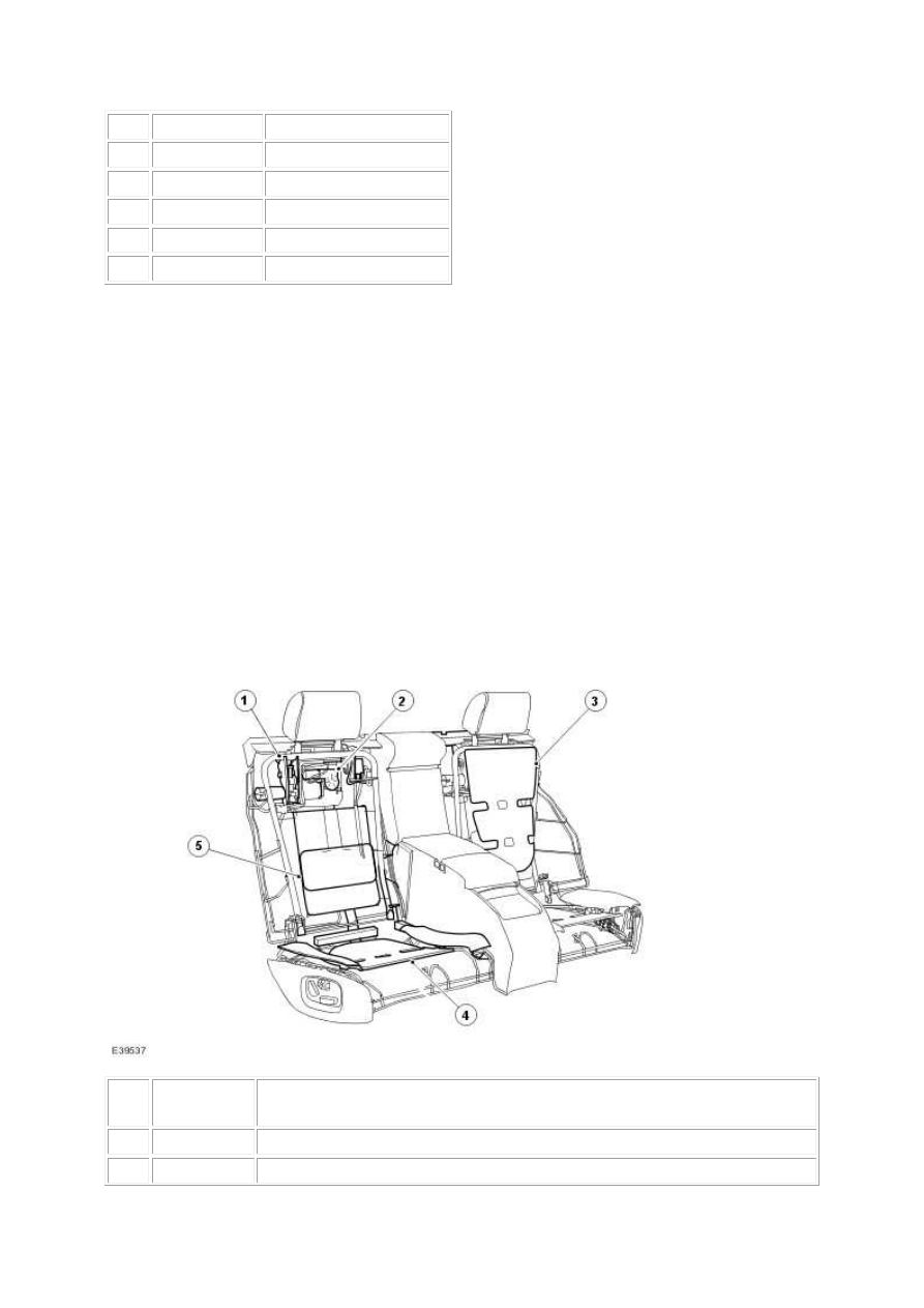
Rear Seat Backrest Motors
Item
Part
Number
Description
1
Rear seat recline motor
2
Rear seat head restraint motor
www.

3
Rear outer seat backrest heater pad (incorporated into the rear outer seat
backrest cushion)
4
Rear outer seat backrest heater pad (incorporated into the rear outer seat
cushion)
5
Rear lumbar motor
The rear outer seat backrests are equipped with electric four way lumbar adjustment, rear seat
head restraint adjustment, and rear outer seat backrest recline adjustment motors. The
electrical functions can be utilized by operating the rear seat control switches and then rear
outer seat backrest memory positions can be stored by the RSM (rear seat module) . The rear
outer seat backrest/headrest can be programmed for up to three different seat memory
configurations. The seat memory switch located within the rear door trim panel can be used to
retrieve the programmed memory configurations.
LUMBAR MOTORS
The front and rear seats have a two or four way lumbar motor system depending on the
specification of the vehicle. The system uses a single motor driven pump, which inflates or
deflates air cells, as required, to provide upper and lower lumbar support. The lumbar motors
are operated from the seat control switches. Depending on the direction the switch is operated
in, one of four solenoids (for 4 way lumbar) or one solenoid (for two way lumbar) housed
within the solenoid pack (integral component of the lumbar assembly) is connected to the
pump, which provides lumbar support by adjusting the amount of air in the appropriate cell.
SEAT MEMORY FUNCTION
he memory control module can store up to three different driver seating, mirror and steering
column positions. The three, numbered memory and single memory store switches control
memory storage and recall operations. Each switch is a momentary action push switch.
Memory Recall
Memory recall has three memory positions stored for the seats, steering column and exterior
mirrors. The switches for this function are located within driver's door trim panel. Pressing the
appropriate numbered memory switch allows the seat to start moving to the position
appropriate to that memory.
The following procedure will store a memory position:
•
Ensure the ignition key is in
•
Ensure reverse gear is not engaged
•
Manually adjust the seat to the desired position, using the seat switches
•
Press and release the 'memory store' switch
•
Press and release the desired numbered memory switch within 5 seconds
A single chime will be emitted from the instrument cluster to indicate that the store operation
has been successful.
When a memory recall is initiated, to limit the overall current consumption, only two-seat axis
will move towards their intended position at any one time. To minimize current load as the
motors start, the initiation of each axis is phased with a 100ms delay between each motor
starting. Memory recall occurs only when the park brake is ON for manual vehicles or the
gear position is in the PARK position for automatic vehicles.
Steering Column Memory
The memory control module controls the electric adjustable steering column in a rake (up and
down) and reach (in and out). The steering column can be adjusted for rake and reach by
operating the rotary joystick control switch on the LH side of the steering column.
To adjust the steering column:
•
Turn the switch to the 'Column' or 'Auto' position
•
Move the switch forwards or backwards to adjust the reach
•
Move the switch up or down to adjust the rake.
Entry/Exit Mode
Entry/Exit mode provides automatic movement of the steering column and driver's seat to
allow easier entry to or exit from the vehicle.
Entry/Exit mode is selected by setting the steering column adjustment switch to the 'AUTO'
position.
NOTE:
If the adjustment switch is moved away from 'AUTO' whilst the steering column is tilted
away, the steering column will move back to it's memorized position when the key is next
inserted in the ignition. Entry/Exit mode will then be cancelled. If the adjustment switch
is moved during entry/exit operation, steering column movement will stop.
www.
Нет комментариевНе стесняйтесь поделиться с нами вашим ценным мнением.
Текст