Jaguar XJ (X350). Manual — part 879

G531330t103 : CHECK THE OPERATION OF THE BRAKE SWITCH (PEDAL
RELEASED)
1. Key off. 2. Disconnect the brake switch electrical connector, CR78. 3. Make sure the brake pedal is
not pressed. 4. Measure the resistance between:
Brake switch connector CR78, component side Brake switch connector CR78, component side
Pin 01
Pin 02
Is the resistance greater than 10 ohms?
-> Yes
GO to Pinpoint Test G531330t104.
-> No
INSTALL a new brake switch. CLEAR the DTC, test the system for normal operation.
G531330t104 : CHECK THE OPERATION OF THE BRAKE SWITCH (PEDAL
PRESSED)
1. Press the brake pedal. 2. Measure the resistance between:
Brake switch connector CR78, component side Brake switch connector CR78, component side
Pin 01
Pin 02
Is the resistance greater than 10 ohms?
-> Yes
INSTALL a new brake switch. CLEAR the DTC, test the system for normal operation.
-> No
GO to Pinpoint Test G531330t105.
G531330t105 : CHECK THE POWER SUPPLY TO THE BRAKE PEDAL SWITCH
1. Key on, engine off. 2. Measure the voltage between:
Brake switch connector CR78, harness side
Battery
Pin 01
Negative terminal

Is the voltage less than 10 volts?
-> Yes
REPAIR the circuit between the brake switch and battery. This circuit includes fuse 44 of the primary
junction box. For additional information, refer to the wiring diagrams. CLEAR the DTC, test the
system for normal operation.
-> No
GO to Pinpoint Test G531330t106.
G531330t106 : CHECK THE BRAKE SWITCH SIGNAL CIRCUIT FOR SHORT
CIRCUIT TO GROUND
1. Key off. 2. Measure the resistance between:
Brake switch connector CR78, harness side
Battery
Pin 02
Negative terminal
Is the resistance less than 10,000 ohms?
-> Yes
REPAIR the short circuit. For additional information, refer to the wiring diagrams. CLEAR the DTC, test
the system for normal operation.
-> No
GO to Pinpoint Test G531330t112.
G531330t112 : CHECK THE BRAKE SWITCH SIGNAL CIRCUIT FOR SHORT
CIRCUIT TO POWER
1. Measure the resistance between:
Brake switch connector CR78, harness side
Battery
Pin 02
Positive terminal
Is the resistance less than 10,000 ohms?
www.

-> Yes
REPAIR the short circuit. For additional information, refer to the wiring diagrams. CLEAR the DTC, test
the system for normal operation.
-> No
GO to Pinpoint Test G531330t113.
G531330t113 : CHECK THE BRAKE SWITCH SIGNAL CIRCUIT FOR HIGH
RESISTANCE
1. Disconnect the ECM electrical connector, EC300. 2. Measure the resistance between:
Brake switch connector CR78, harness side ECM connector EC300, harness side
Pin 02
Pin 41
Is the resistance greater than 5 ohms?
-> Yes
REPAIR the high resistance circuit. For additional information, refer to the wiring diagrams. CLEAR the
DTC, test the system for normal operation.
-> No
REFER to the warranty policy and procedures manual if an ECM is suspect.
Removal and installation
Brake Pedal Position (BPP) Switch
Removal
1 . Switch the ignition on.
2 . Position the front seat fully rearwards.
3 . Switch the ignition off.
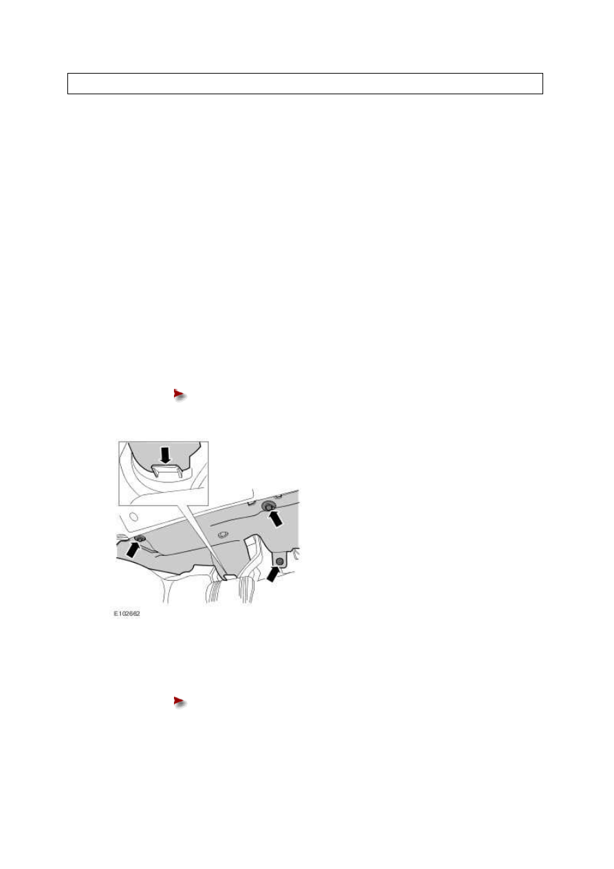
4 . Remove the driver's side footwell trim panel.
Release the 3 clips.
5 . Release the brake pedal position (BPP) switch.
Rotate the BPP switch 45 degrees counter-clockwise.
www.
Нет комментариевНе стесняйтесь поделиться с нами вашим ценным мнением.
Текст