Jaguar XJ (X350). Manual — part 256

-> No
REPAIR the short circuit. For additional information, refer to the wiring diagrams. Clear the DTC, test
the system for normal operation by driving the vehicle at more than 20 kph (12.5 mph) for more than
3 minutes.
G531322t103 : CHECK THE WSS SIGNAL CIRCUIT FOR SHORT CIRCUIT TO
GROUND
1. Measure the resistance between:
CV008, harness side
Battery
Pin 02
Negative terminal
•
Is the resistance greater than 100 Kohms?
-> Yes
GO to Pinpoint Test
G531322t104
.
-> No
REPAIR the short circuit. For additional information, refer to the wiring diagrams. Clear the DTC, test
the system for normal operation by driving the vehicle at more than 20 kph (12.5 mph) for more than
3 minutes.
G531322t104 : CHECK THE WSS SIGNAL CIRCUIT FOR HIGH RESISTANCE
1. Measure the resistance between:
CV008, harness side EC030, harness side
Pin 02
Pin 43
•
Is the resistance less than 10 ohms?
-> Yes
GO to Pinpoint Test
G531322t105
.
-> No
REPAIR the high resistance circuit. For additional information, refer to the wiring diagrams. Clear the
DTC, test the system for normal operation by driving the vehicle at more than 20 kph (12.5 mph) for
more than 3 minutes.
G531322t105 : CHECK THE WSS SIGNAL AND RETURN CIRCUITS FOR SHORT
CIRCUIT TO EACH OTHER
1. Measure the resistance between:
CV008, harness side CV008, harness side
Pin 01
Pin 02
•
Is the resistance greater than 100 Kohms?
-> Yes
An intermittent fault may be present in the wiring harness. Visually check for chaffed wires or other
physical damage to the harness. If no fault is found in the harness, suspect the following
components: - WSS connector - WSS - ABS module connector - ABS module
-> No
REPAIR the short circuit. For additional information, refer to the wiring diagrams. Clear the DTC, test
the system for normal operation by driving the vehicle at more than 20 kph (12.5 mph) for more than
3 minutes.
PINPOINT TEST G531322p8 : BOOSTER
PRESSURE SENSOR
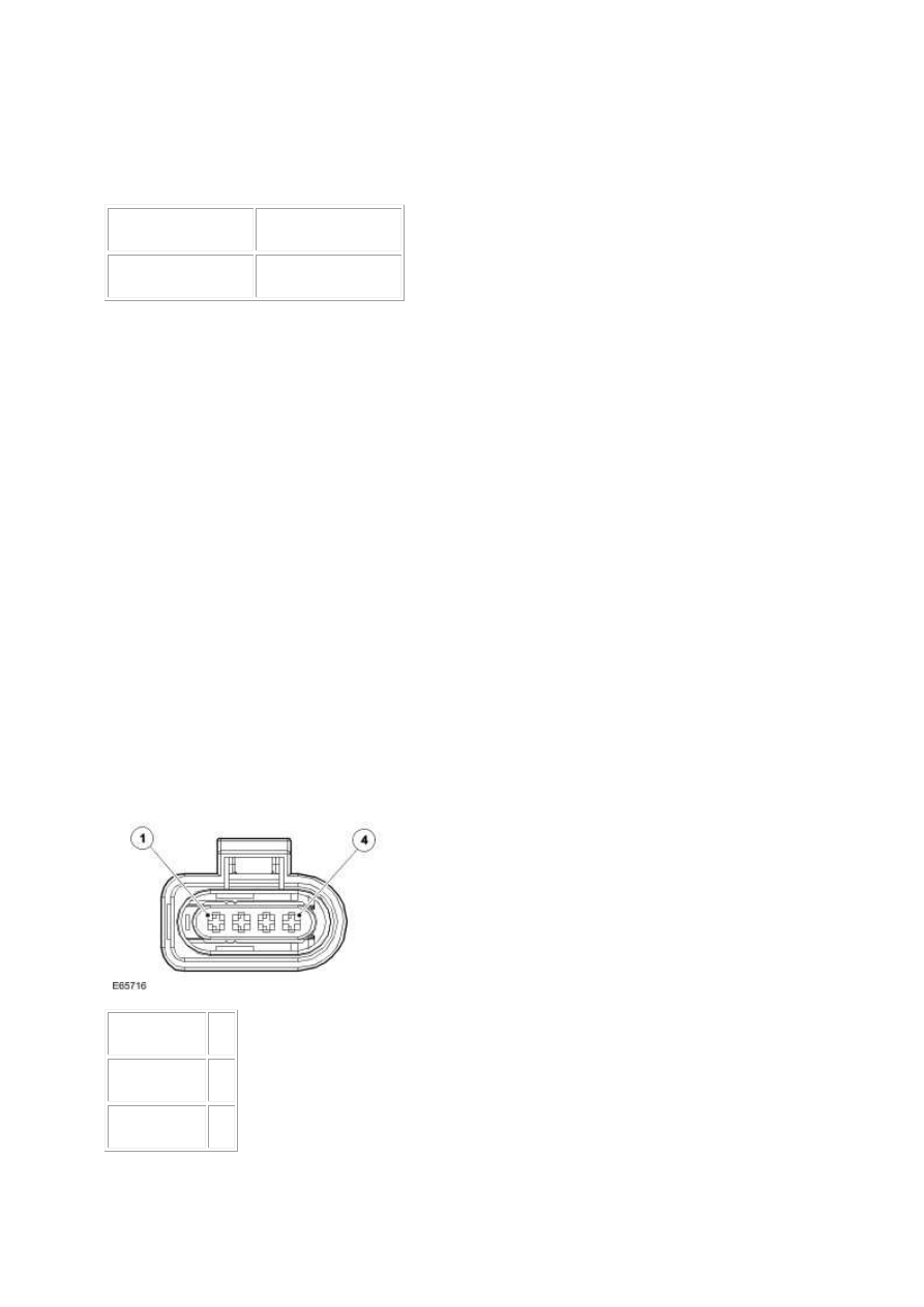
G531322t25 : CHECK THE POWER SUPPLY TO THE BOOSTER PRESSURE
SENSOR
1.
Circuit
Pin
Power supply 03
Signal A
04
www.
Signal B
01
Ground
02
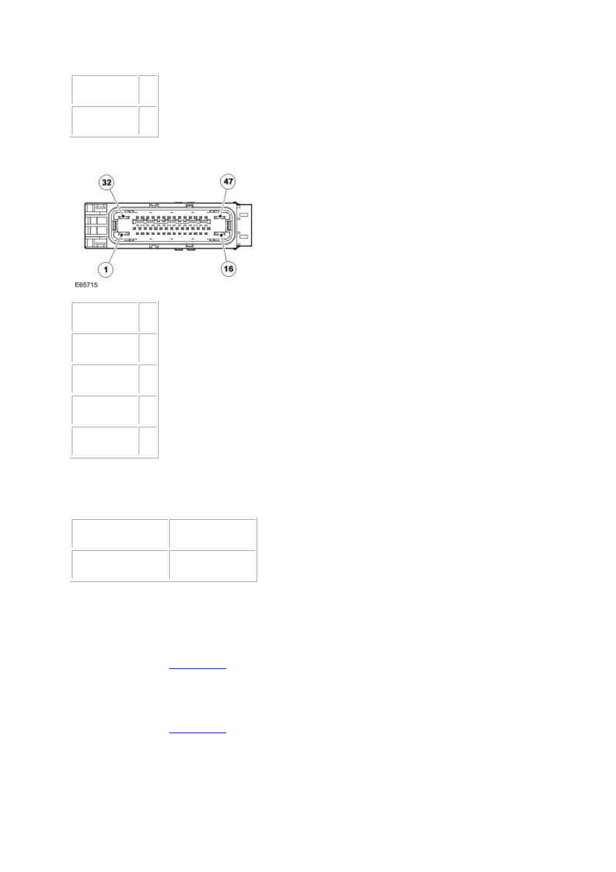
2.
Circuit
Pin
Power supply 26
Signal A
38
Signal B
30
Ground
27
3. Key off. 4. Disconnect the booster pressure sensor connector, EC095. 5. Key on, engine off. 6.
Measure the voltage between:
EC095, harness side
Battery
Pin 03
Negative terminal
•
Is the voltage greater than 4 volts?
-> Yes
GO to Pinpoint Test
G531322t28
.
-> No
GO to Pinpoint Test
G531322t26
.

G531322t26 : CHECK THE BOOSTER PRESSURE SENSOR POWER SUPPLY
CIRCUIT FOR SHORT CIRCUIT TO GROUND
1. Measure the resistance between:
EC095, harness side
Battery
Pin 03
Negative terminal
•
Is the resistance greater than 10 Kohms?
-> Yes
GO to Pinpoint Test
G531322t27
.
-> No
REPAIR the short circuit. For additional information, refer to the wiring diagrams. Clear the DTC, test
the system for normal operation by applying and releasing the brake pedal firmly three times with
the engine running.
G531322t27 : CHECK THE BOOSTER PRESSURE SENSOR POWER SUPPLY
CIRCUIT FOR HIGH RESISTANCE
1. Key off. 2. Disconnect the ABS module connector, EC030. 3. Measure the resistance between:
EC095, harness side EC030, harness side
Pin 03
Pin 26
•
Is the resistance less than 10 ohms?
-> Yes
An intermittent fault may be present in the wiring harness. Visually check for chaffed wires or other
physical damage to the harness.
-> No
REPAIR the high resistance circuit. For additional information, refer to the wiring diagrams. Clear the
DTC, test the system for normal operation by applying and releasing the brake pedal firmly three
times with the engine running.
G531322t28 : CHECK THE GROUND CIRCUIT TO THE BOOSTER PRESSURE
SENSOR
1. Measure the resistance between:
www.
Нет комментариевНе стесняйтесь поделиться с нами вашим ценным мнением.
Текст