Jaguar XJ (X350). Manual — part 771
This subsequent combustion of the unburnt and partially burnt carbon monoxide (CO) and
hydrocarbon (HC) particles help to reduce the emission of these pollutants from the exhaust system.
The additional heat generated in the exhaust manifold also provides rapid heating of the exhaust
system catalytic converters. The additional oxygen which is delivered to the catalytic converters also
generates an exothermic reaction which causes the catalytic converters to reach their optimum
operating temperature and 'light off' quickly.
The catalytic converters only start to provide effective treatment of emission pollutants when they
reach an operating temperature of approximately 250°C (482°F) and need to be between
temperatures of 400°C (752°F) and 800°C (1472°F) for optimum efficiency. Consequently, the heat
produced by the AIR 'afterburning' reduces the time delay before the catalysts reach an efficient
operating temperature.
The AIR system comprises the following components:
AIR pump
AIR switching valve
AIR control valve
AIR vacuum reservoir
AIR pump relay
AIR pressure sensor (North American specification vehicles only)
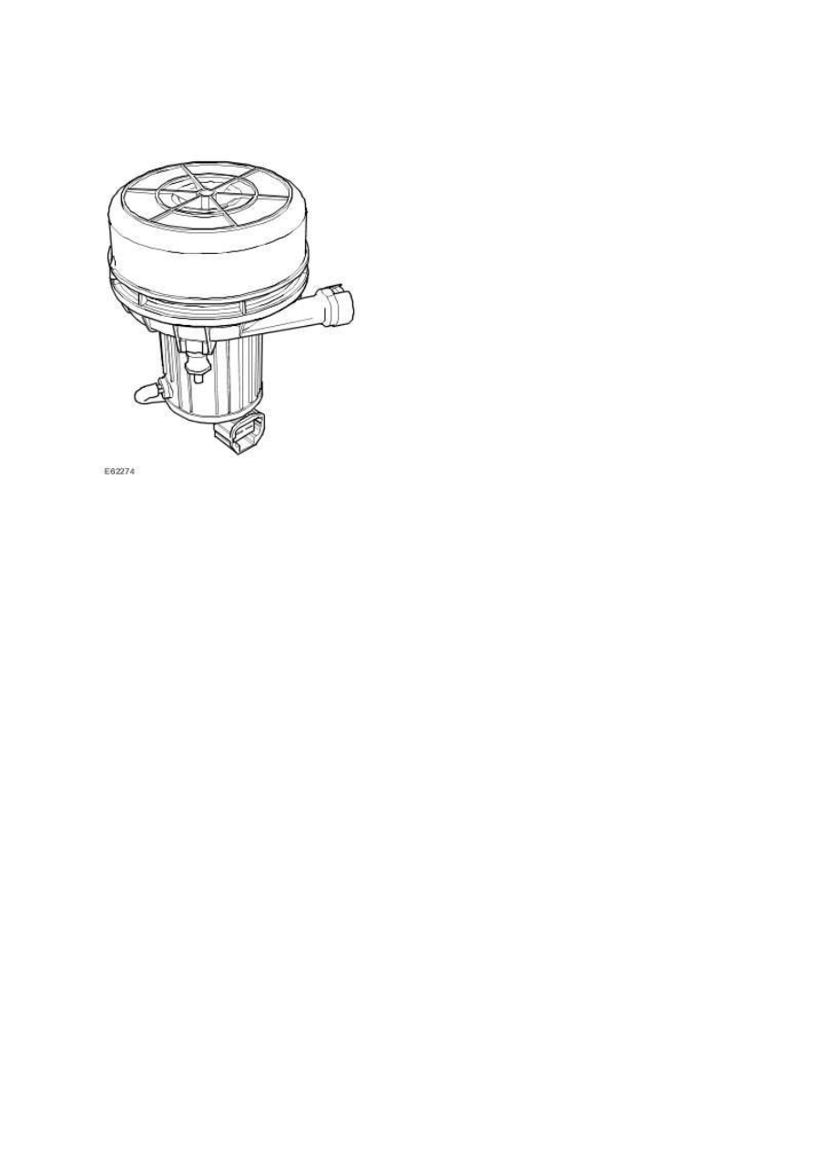
AIR Pump
The AIR pump is located behind the right-hand side of the front bumper cover. The pump is fitted on
rubber mountings to help prevent noise which is generated by AIR pump operation. The AIR pump is
powered from the vehicle battery by a dedicated relay and supplies approximately 10 to 15 kg/hr (22
to 33 lb/hr) of air when the engine is at idle speed and the ambient temperature is below 20°C
(68°F).
Air is drawn into the AIR pump through vents in its front cover and is then passed through a foam
filter. The air is delivered to the exhaust manifold on each side of the engine through a combination
of plastic pipes and stainless steel tubes.
One second after the AIR pump is energised, the ECM switches on the AIR switching valve, which
opens to allow vacuum from the AIR vacuum reservoir to be applied to the vacuum operated AIR
control valve. When the vacuum is applied to the AIR control valve, it opens to allow the air from the
AIR pump through to the exhaust manifolds.
When the ECM switches off the AIR switching valve, the vacuum supply to the AIR control valve is
cut-off and the valve closes to prevent further air being injected into the exhaust manifolds. With an
approximate five second delay after as the AIR switching valve is closed, the ECM removes power
from the AIR pump relay, and this in turn stops the AIR pump from operating.
www.
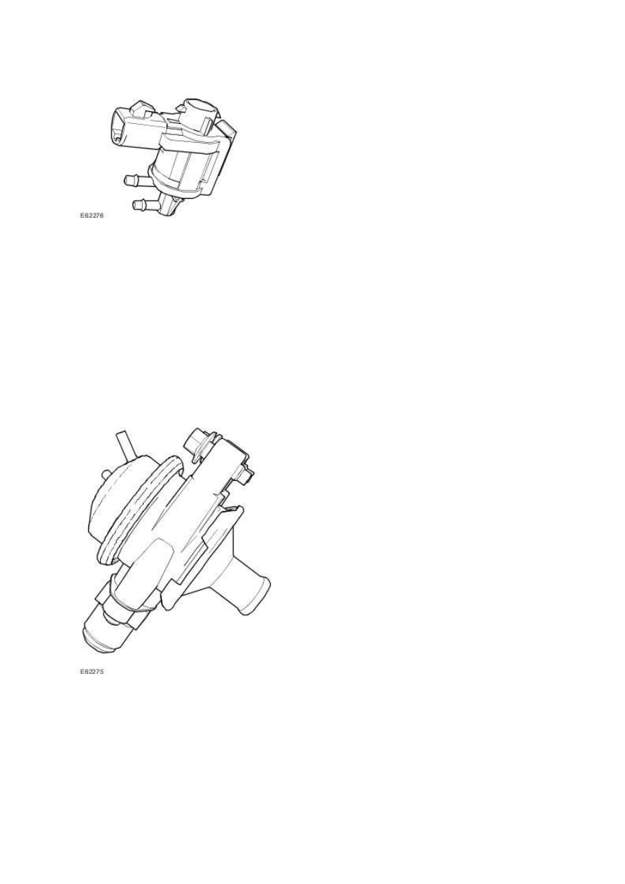
AIR Switching Valve
The ECM switches on the AIR switching valve with a one second delay after initiating AIR pump
operation. When the AIR switching valve is open, a steady vacuum supply is allowed through to open
the vacuum operated AIR control valve. When the ECM switches off the AIR switching valve, the
valve closes and immediately shuts off the vacuum supply to the AIR control valve. The pump
continues to operate for a further five seconds for system diagnostic purposes.
When the AIR switching valve is switched off, the vacuum supply line opens to atmosphere, and this
causes the AIR switching valve to close automatically to prevent any further injection of air.
AIR Control Valve
The injected air from the AIR pump is controlled by the AIR control valve. This allows the correct
amount of air to be injected directly into the exhaust manifolds. The AIR control valve prevents
exhaust gasses from blowing back into the AIR pump.
The AIR control valve is assisted in operation by a vacuum source from the AIR vacuum reservoir
located in the right-hand side of the engine bay. This assistance allows the actuation of the AIR
control valve independently from the intake manifold vacuum levels available.
When the pressure in the exhaust system is higher than in the AIR system, the AIR control valve
closes the circuit, and this protects the AIR system from exhaust gasses blowing back into the AIR
system.
Vacuum to the AIR switching valve is provided from the intake manifold vacuum by the AIR vacuum
reservoir. A small bore vacuum hose provides the vacuum route between the AIR vacuum reservoir
and AIR switching valve. A further small bore vacuum hose is used to connect the AIR switching valve
to the AIR control valve.
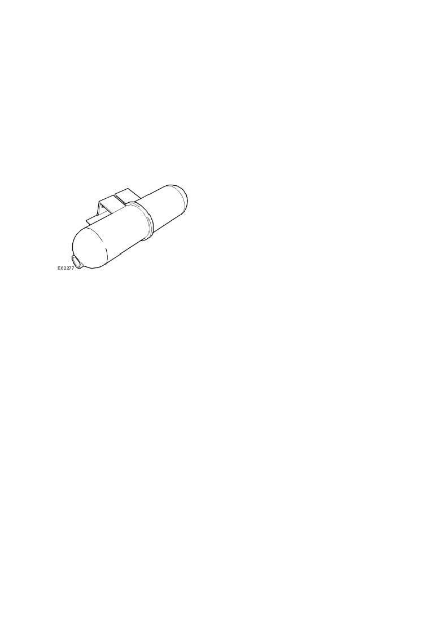
AIR Vacuum Reservoir
The AIR vacuum reservoir is located on the right-hand side of the engine bay.
The AIR vacuum reservoir is included in the vacuum supply line between the intake manifold and the
AIR switching valve.
The AIR vacuum reservoir contains a one-way valve to stop vacuum leaking back towards the intake
manifold side. The AIR vacuum reservoir holds a constant vacuum so that the AIR control valve opens
as soon as the AIR switching valve is switched on.
AIR Pump Relay
The AIR pump relay is located on the AIR pump mounting bracket. The ECM is used to control the
operation of the AIR pump by the AIR pump relay.
The AIR system receives its voltage supply through the AIR pump relay. The ECM monitors the state
of the relay for correct operation as part of its system diagnostic.
AIR Pressure Sensor - North American specification vehicles only
The AIR system is monitored by measuring the system pressure by using the AIR pressure sensor at
several instances during its cycle of operation.
The AIR system pressure is measured before operation of the AIR pump. The AIR pump is then
switched on and with a one second delay, the AIR switching valve is opened. After a stabilizing
period, the system pressure is measured again, this time by taking the average of a one second
duration of readings, and normalising for variations in battery voltage and atmospheric pressure. If
the system pressure measured at this time has not risen enough with respect to the initial AIR
www.
Нет комментариевНе стесняйтесь поделиться с нами вашим ценным мнением.
Текст