Jaguar XJ (X350). Manual — part 1566

proceeding to the next step.
5 . If the cause is not visually evident, check for Diagnostic Trouble Codes (DTCs) and refer
to the DTC Index.
Symptom Chart
Warning Lamp
Flash/Audible
Tone
DTC
Symptom
Possible Cause
Action
Unlit
N/A
No
communication
with RCM
•
Data link
connector (DLC)
fault
•
RCM supply
circuits - open
circuit, short
circuit to ground,
short circuit to
power
•
SCP circuit -
open circuit,
short circuit to
ground, short
circuit to power
Refer to the electrical
circuit diagrams and
check DLC, RCM, and
SCP circuits for short,
open circuit
Unlit
N/A
Air bag warning
lamp inoperative
•
Warning lamp
circuit - short
circuit to ground
•
Warning lamp
failure
Refer to electrical
circuit diagrams, notes
and check restraint
control module, power
circuit for fault, for
additional information,
GO to Pinpoint Test
G1043827p1.
Unlit
DTC
B2477
No
communication
with RCM
•
Module software
option content
not programmed
or incorrectly
programmed
The module can be
configured using the
new module procedure.
Check and configure as
required
DTC Index
Supplemental Restraint System
CAUTION: When probing connectors to take measurements in the course of the
pinpoint tests, use the adaptor kit, part number 3548-1358-00
NOTE:
If the control module/component is suspect and the vehicle remains under manufacturer
warranty, refer to the Warranty Policy and Procedures manual (section B1.2), or
determine if any prior approval program is in operation, prior to the installation of a new
module/component.
NOTE:
When performing voltage or resistance tests, always use a digital multimeter (DMM)
accurate to three decimal places and with a current calibration certificate. When testing
resistance, always take the resistance of the DMM leads into account.
NOTE:
Check and rectify basic faults before beginning diagnostic routines that involve pinpoint
tests.
NOTE:
Inspect connectors for signs of water ingress, and pins for damage and/or corrosion.
NOTE:
If DTCs are recorded and, after performing the pinpoint tests, a fault is not present, an
intermittent concern may be the cause. Always check for loose connections and corroded
terminals.
Reading restraints flash codes
Self-check
Turn the ignition switch to the ON position
•
Warning light ON solid for 6 seconds
•
Warning light OFF
Fault on system
Turn the ignition switch to the ON position.
Warning light ON solid for 6 seconds
Warning light OFF for 2 seconds
Warning light flashes the appropriate number of times for the fault logged (see table)
Warning light OFF for 2 seconds
The sequence is repeated 5 times
www.
Warning light ON until the ignition is turned OFF
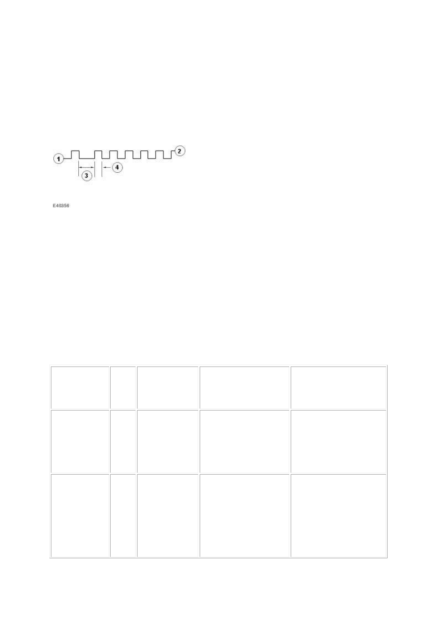
Example:- Flash code 16 would be shown as lamp ON for one occurrence of 0.5 second then
lamp OFF for one second, then six occurrences of lamp ON for 0.5 seconds each (1-6).
•
1. Lamp OFF
•
2. Lamp ON
•
3. Time between first digit and second digit (1 second)
•
4. Time ON of each flash of the second digit (0.5 second)
Priority
Priority is not assigned to any of the flash codes. They are displayed depending on which code
is identified first. If multiple faults are present only one will be flashed. That fault will need to
be rectified before the next code will be made available.
If the driver warning lamp is inoperative and a fault occurs, an audible chime will be sounded
90 seconds after the ignition is turned ON.
Warning
Lamp
Flash/Audible
Tone
DTC
Description
Possible Causes
Action
Lamp fault
code = 13
B1231
Longitudinal
Acceleration
Threshold
Exceeded
•
Restraint control
module, crash
data memory full
Suspect restraint control
module, fault. Check and
install as required, refer to
the new module
installation note at the top
of the DTC Index
Continuous
lamp
B1317
Battery Voltage
High
•
Restraint control
module, power
supply voltage -
high (above 15
V +/- 8%)
•
Battery voltage
is regulated by
engine control
Refer to electrical circuit
diagrams, notes and check
restraint control module,
power circuit for fault

module
Continuous
lamp
B1318
Battery Voltage
Low
•
Restraint control
module, power
supply voltage -
low (below 10.4
V +/- 8%)
Refer to electrical circuit
diagrams, notes and check
restraint control module,
power and ground circuit
for fault
Lamp fault
code = 12
B1342 ECU Fault
•
Restraint control
module, internal
fault
Suspect restraint control
module, fault. Check and
install as required, refer to
the new module
installation note at the top
of the DTC Index
Tone sounds if
fault present
B1869
Lamp Air Bag
Warning
Indicator Circuit
Open
•
Restraint control
module,
instrument
cluster airbag
warning
indicator circuit -
short to ground
or open circuit
Carry out any pinpoint
tests associated with this
DTC using the
manufacturer approved
diagnostic system. Refer
to electrical circuit
diagrams, notes and check
instrument cluster airbag
warning indicator circuit
for short to ground or
open circuit, for
additional information,
GO to Pinpoint Test
G1043827p2.
Tone sounds if
fault present
B1870
Lamp Air Bag
Warning
Indicator Circuit
Short To Power
•
Restraint control
module,
instrument
cluster airbag
warning
indicator circuit -
short to power
Carry out any pinpoint
tests associated with this
DTC using the
manufacturer approved
diagnostic system. Refer
to electrical circuit
diagrams, notes and check
instrument cluster airbag
warning indicator circuit
for short to power, for
additional information,
GO to Pinpoint Test
G1043827p2.
Lamp fault
code = 18
B1884
PAD Warning
Lamp Circuit
Failure
•
Restraint control
module,
passenger airbag
deactivation
indicator circuit -
open circuit or
Carry out any pinpoint
tests associated with this
DTC using the
manufacturer approved
diagnostic system. Refer
to electrical circuit
diagrams, notes and check
www.
Нет комментариевНе стесняйтесь поделиться с нами вашим ценным мнением.
Текст