Jaguar XJ (X350). Manual — part 1166
Does the throttle motor relay make an audible click?
-> Yes
GO to Pinpoint Test G240070t17.
.
-> No
GO to Pinpoint Test G240070t22.
.
G240070t17 : CHECK THE ECM POWER SUPPLY FROM THE THROTTLE
MOTOR RELAY
1. Measure the voltage between the throttle motor relay connector FH 32D pin 5 (NR) and ground.
Is the voltage greater than 10 volts?
-> Yes
GO to Pinpoint Test G240070t18.
.
-> No
GO to Pinpoint Test G240070t19.
.
G240070t18 : CHECK CONTINUITY OF THE ECM POWER SUPPLY WIRE FROM
THE THROTTLE MOTOR RELAY
1. Turn the ignition switch to the OFF position. 2. Disconnect the ECM electrical connector PI 1 and
remove the throttle motor relay. 3. Measure the resistance between the throttle motor relay
electrical connector FH 32D pin 5 (NR) and the ECM electrical connector PI 1 pin 134 (GU).
Is the resistance less than 5 ohms?
-> Yes
DIAGNOSE the electronic engine control system. For additional information, refer to <<303-14>>.
-> No
REPAIR the ECM power supply wire from the throttle motor relay. CLEAR the DTC. TEST the system
for normal operation.
G240070t19 : CHECK FUSE 18 IN THE FRONT POWER DISTRIBUTION BOX
(FPDB)
1. Check the fuse.
Is the fuse OK?
-> Yes
GO to Pinpoint Test G240070t20.
.
-> No
GO to Pinpoint Test G240070t21.
.
G240070t20 : CHECK THE THROTTLE MOTOR RELAY POWER SUPPLY
CIRCUIT
1. Remove the throttle motor relay. 2. Measure the voltage between the throttle motor relay
connector FH 32D pin 3 (YR) and ground.
Is the voltage less than 10 volts?
-> Yes
REPAIR the throttle motor relay power supply circuit. CLEAR the DTC. TEST the system for normal
operation.
-> No
INSTALL a new throttle motor relay. CLEAR the DTC. TEST the system for normal operation.
G240070t21 : CHECK FUSE 18 FOR A SHORT TO GROUND
1. Measure the resistance between fuse 18 and ground.
Is the resistance greater than 10,000 ohms?
-> Yes
INSTALL a new fuse. CLEAR the DTC. TEST the system for normal operation.
-> No
REPAIR short to ground between engine compartment fuse box and the throttle motor relay. INSTALL
a new fuse. CLEAR the DTC. TEST the system for normal operation.
G240070t22 : CHECK THE POWER SUPPLY CIRCUIT TO THE THROTTLE
MOTOR RELAY COIL
1. Turn the ignition switch to the RUN position. 2. Measure the voltage between the throttle motor
relay connector FH 32D pin 1 (GR) and ground.
Is the voltage greater than 10 volts?
-> Yes
GO to Pinpoint Test G240070t23.
.
-> No
www.
REPAIR the throttle motor relay coil power supply circuit from the engine compartment fuse box.
CLEAR the DTC. TEST the system for normal operation.
G240070t23 : CHECK CONTINUITY OF THE THROTTLE MOTOR RELAY COIL
1. Remove the throttle motor relay (if not already removed). 2. Measure the resistance between
terminal 1 and terminal 2 of the throttle motor relay.
Is the resistance between 70 and 90 ohms?
-> Yes
GO to Pinpoint Test G240070t24.
.
-> No
INSTALL a new throttle motor relay. CLEAR the DTC. TEST the system for normal operation.
G240070t24 : CHECK CONTINUITY OF THE THROTTLE MOTOR RELAY
GROUND CIRCUIT
1. Disconnect the ECM electrical connector PI 1. 2. Measure the resistance between the throttle
motor relay electrical connector FH 32D pin 2 (GR) and the ECM electrical connector PI 1 pin 52 (GR).
Is the resistance less than 5 ohms?
-> Yes
DIAGNOSE the electronic engine control system. For additional information, refer to <<303-14>>.
-> No
REPAIR the throttle motor relay ground circuit from the ECM to the engine compartment fuse box.
CLEAR the DTC. TEST the system for normal operation.
PINPOINT TEST G240070p5 : DTC P1243
G240070t25 : CHECK THE ACCELERATOR PEDAL DEMAND SENSOR GROUND
CIRCUIT
1. Disconnect the ECM electrical connector PI 1 and the accelerator pedal electrical connector CA 88.
2. Measure the resistance between PI 1 pin 19 (BG) and CA 88 pin 6 (BG). 3. Measure the resistance
between PI 1 pin 20 (BG) and CA 88 pin 3 (BG).
Is the resistance less than 5 ohms?
-> Yes
DIAGNOSE the electronic engine control system. For additional information, refer to <<303-14>>.
-> No
REPAIR the accelerator pedal demand sensor ground circuit from the accelerator pedal to the ECM.
CLEAR the DTC. TEST the system for normal operation.
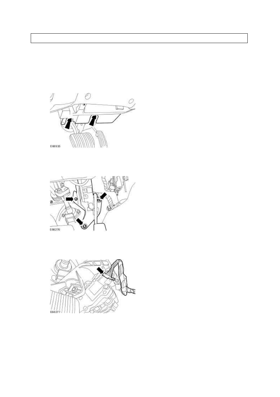
Removal and installation
Accelerator Pedal (19.20.01)
Removal
1 . Remove the driver side instrument panel lower trim panel.
2 . Detach the accelerator pedal retaining bracket.
3 . Disconnect the accelerator pedal electrical connector.
4 . Detach the accelerator pedal wiring harness.
www.
Нет комментариевНе стесняйтесь поделиться с нами вашим ценным мнением.
Текст