Jaguar XJ (X350). Manual — part 1039
The impeller, which is driven by the engine, imparts a circular flow to the transmission fluid in the
converter.
This transmission fluid strikes the turbine wheel, which causes the flow to change its direction.
The transmission fluid flows out of the turbine wheel close to the hub and strikes the stator,
where its direction is changed again to a direction suitable for re-entering the impeller.
The change in direction at the stator generates a torque reaction that increases the torque
reaching the turbine.
The ratio between turbine and impeller torque is referred to as torque multiplication or
conversion.
The greater the difference in speeds of rotation at the impeller and turbine, the greater the
increase in torque; The maximum increase is obtained when the turbine wheel is stationary.
As turbine wheel speed increases, the amount of torque multiplication gradually drops.
When the turbine wheel is rotating at about 85 % of the impeller speed, torque conversion
reverts to 1, that is to say torque at the turbine wheel is no higher than the torque at the
impeller.
The stator, which is prevented from rotating backwards by a freewheel and the shaft in the
transmission housing, runs freely in the transmission fluid flow and overruns the freewheel.
From this point on, the converter acts only as a fluid coupling. During the torque conversion
process, the stator ceases to rotate and bears against the housing by the freewheel.
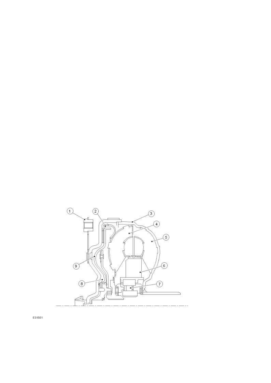
Torque converter

1
Torque converter retaining plate
2
Lock-up clutch lined plate
3
Torque converter cover
4
Turbine
5
Impeller
6
Stator
7
Stator freewheel
8
Space behind lock-up clutch
9
Lock-up clutch piston
Torque Converter Lock-up Clutch
The torque converter lock-up clutch is a device that eliminates slip in the torque converter and
therefore helps to keep fuel consumption to a minimum.
The torque converter lock-up clutch is engaged and released by the control system. During the
actuating phase, a slight difference is selected between the impeller and turbine wheels.
Pressure at the torque converter lock-up clutch piston is determined by an electronic pressure
control valve.
The torque converter lock-up clutch can be controlled and engaged in any gear from 1 to 6. When
decoupling takes place the actuating clutch A in the transmission is dependent on load and output
speed.
When the torque converter lock-up clutch is released, transmission fluid pressures behind the lock-
up clutch piston turbine area are equalized. The direction of flow is through the turbine shaft and the
area behind the piston into the turbine area.
To engage the torque converter lock-up clutch the direction of transmission fluid flow is changed and
reversed by a valve in the hydraulic control unit. At the same time the space behind the torque
converter lock-up clutch piston is vented.
Oil pressure extends from the turbine area to the torque converter lock-up clutch piston and presses
it against the cover outer shell of the torque converter. This locks the turbine wheel by way of the
lined disc between the piston and the cover and enables the drive to pass with limited slip to the
planetary gear train in normal operating conditions.
Item
Part Number
Description
www.

Geartrain
Power is transmitted from the torque converter to the planetary gearsets through the input shaft.
Clutches are used to hold and drive certain combinations of gearsets. This results in six forward ratios
and one reverse ratio, which are transmitted to the output shaft and differential.
Gear Ratio
Gear ratios
1st
4.17:1
2nd
2.34:1
3rd
1.52:1
4th
1.14:1
5th
0.87:1
6th
0.69:1
Rev
3.40:1
Single Planetary Gearset
The single planetary gear overdrive carrier is driven by the input shaft.
The single planetary gear set consists of:
1 sunwheel
4 planetary gears meshing with the sunwheel
1 planetary gear carrier
1 ring gear
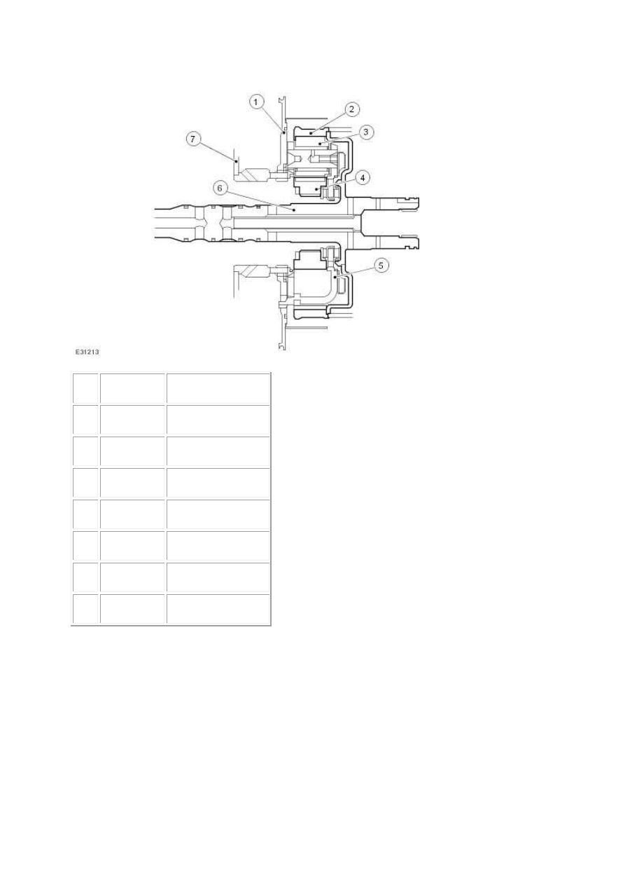
Single Planetary Gearset
Item
Part Number
Description
1
Baffle plate A
2
Ring gear
3
Planetary gear 1
4
Sunwheel
5
Planetary gear spider
6
Turbine shaft
7
Cylinder A
Double Planetary Gearset
The double planetary gearset is splined to the output shaft.
The double planetary gear set consists of:
2 sunwheels of different sizes
3 short planetary gears meshing with the sunwheels
3 long planetary gears meshing with the sunwheels
www.
Нет комментариевНе стесняйтесь поделиться с нами вашим ценным мнением.
Текст