Jaguar XJ (X350). Manual — part 874

G531330t100 : CHECK THE FRP SENSOR SUPPLY CIRCUIT VOLTAGE
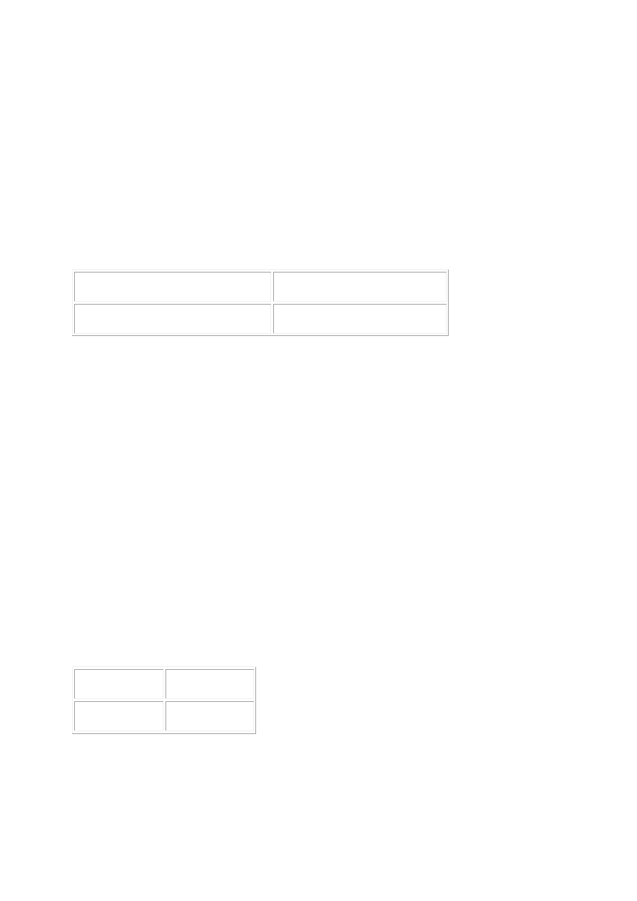
1. Disconnect the FRP sensor electrical connector, IL12. 2. Key on, engine off. 3. Measure the voltage
between:
FRP sensor connector IL12, harness side
Battery
Pin 01
Negative terminal
Is the voltage less than 4 volts?
-> Yes
REPAIR the 5 volt supply circuit between the FRP sensor and the ECM. For additional information,
refer to the wiring diagrams. CLEAR the DTC and test the system for normal operation.
-> No
GO to Pinpoint Test G531330t101.
G531330t101 : CHECK THE FRP SENSOR SUPPLY CIRCUIT FOR SHORT
CIRCUIT TO POWER
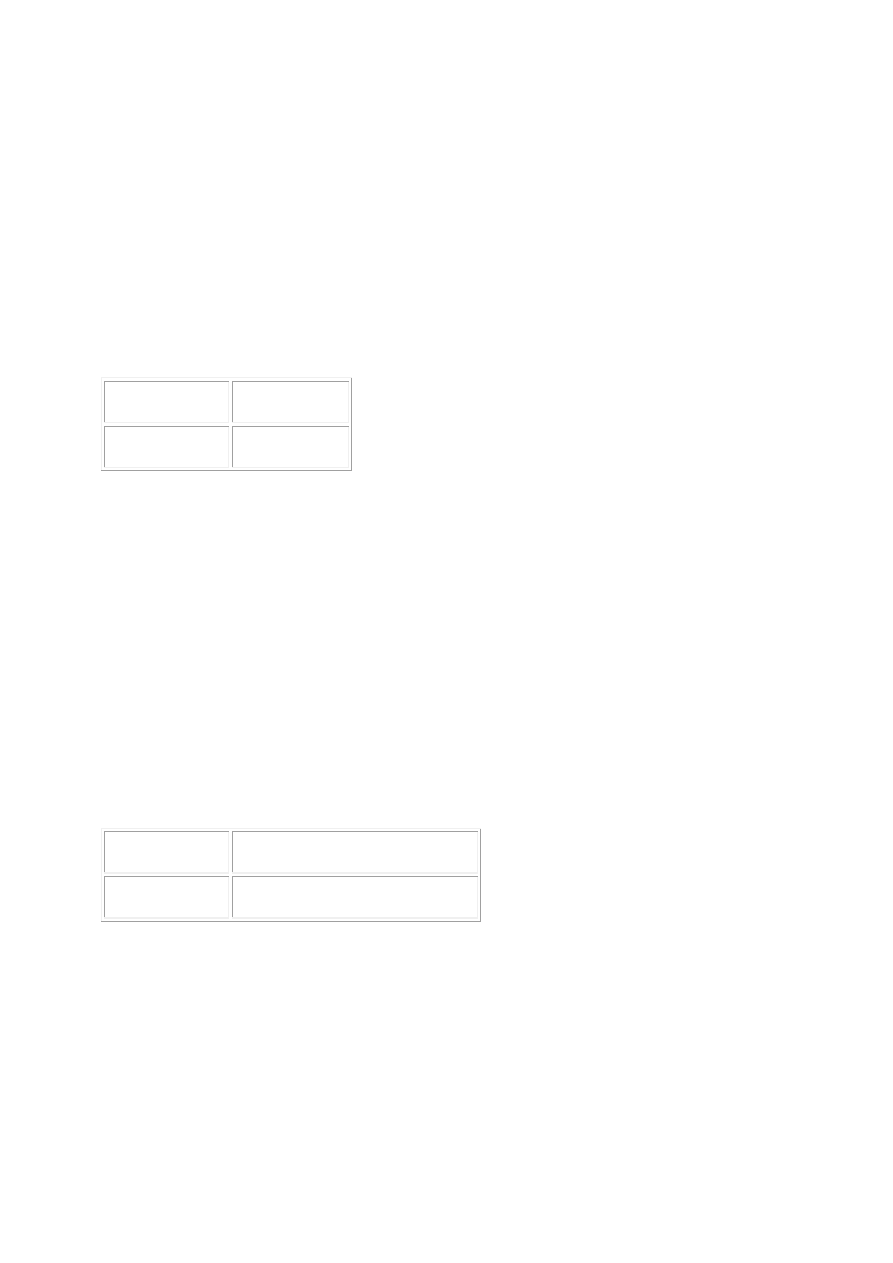
1. Key off. 2. Measure the resistance between:
FRP sensor connector IL12, harness side
Battery
Pin 01
Positive terminal
Is the resistance less than 10,000 ohms?
-> Yes
REPAIR the short circuit. For additional information, refer to the wiring diagrams. CLEAR the DTC and
test the system for normal operation.
-> No
GO to Pinpoint Test G531330t102.
G531330t102 : CHECK THE FRP SENSOR SIGNAL CIRCUIT FOR SHORT
CIRCUIT TO GROUND
1. Measure the resistance between:
FRP sensor connector IL12, harness side
Battery

Pin 03
Negative terminal
Is the resistance less than 10,000 ohms?
-> Yes
REPAIR the short circuit. For additional information, refer to the wiring diagrams. CLEAR the DTC and
test the system for normal operation.
-> No
GO to Pinpoint Test G531330t107.
G531330t107 : CHECK THE FRP SENSOR SIGNAL CIRCUIT FOR SHORT
CIRCUIT TO POWER
1. Measure the resistance between:
FRP sensor connector IL12, harness side
Battery
Pin 03
Positive terminal
Is the resistance less than 10,000 ohms?
-> Yes
REPAIR the short circuit. For additional information, refer to the wiring diagrams. CLEAR the DTC and
test the system for normal operation.
-> No
GO to Pinpoint Test G531330t108.
G531330t108 : CHECK THE FRP SENSOR SIGNAL CIRCUIT FOR HIGH
RESISTANCE
1. Disconnect the ECM sensor electrical connector, PI300. 2. Measure the resistance between:
FRP sensor connector IL12, harness side ECM connector PI300, harness side
Pin 03
Pin 71
Is the resistance greater than 5 ohms?
www.
-> Yes
REPAIR the high resistance circuit. For additional information, refer to the wiring diagrams. CLEAR the
DTC and test the system for normal operation.
-> No
GO to Pinpoint Test G531330t110.
G531330t110 : CHECK THE FRP SENSOR GROUND CIRCUIT FOR HIGH
RESISTANCE
1. Measure the resistance between:
FRP sensor connector IL12, harness side ECM connector PI300, harness side
Pin 02
Pin 10
Is the resistance greater than 5 ohms?
-> Yes
REPAIR the high resistance circuit. For additional information, refer to the wiring diagrams. CLEAR the
DTC and test the system for normal operation.
-> No
INSTALL a new FRP sensor.
Fuel Rail Pressure (FRP) Sensor (18.30.98) CLEAR the DTC and test the system for normal operation.
PINPOINT TEST G531330p27 :
STARTER RELAY SIGNAL
G531330t87 : CHECK THE STARTER RELAY TO ECM CIRCUIT FOR SHORT
CIRCUIT TO GROUND
1. Key off. 2. Remove the starter relay. 3. Measure the resistance between:
Starter relay base
Battery
Pin 02
Negative terminal
Is the resistance less than 10,000 ohms?
-> Yes
REPAIR the short circuit. For additional information, refer to the wiring diagrams. CLEAR the DTC and
test the system for normal operation.
-> No
GO to Pinpoint Test G531330t134.
G531330t134 : CHECK THE STARTER RELAY TO ECM CIRCUIT FOR SHORT
CIRCUIT TO POWER
1. Measure the resistance between:
Starter relay base
Battery
Pin 02
Positive terminal
Is the resistance less than 10,000 ohms?
-> Yes
REPAIR the short circuit. For additional information, refer to the wiring diagrams. CLEAR the DTC and
test the system for normal operation.
-> No
GO to Pinpoint Test G531330t133.
G531330t133 : CHECK THE STARTER RELAY TO ECM CIRCUIT FOR HIGH
RESISTANCE
1. Disconnect the ECM electrical connector, EC300. 2. Measure the resistance between:
Starter relay base ECM connector EC300, harness side
Pin 02
Pin 51
Is the resistance greater than 5 ohms?
-> Yes
REPAIR the high resistance circuit. For additional information, refer to the wiring diagrams. CLEAR the
DTC and test the system for normal operation.
-> No
www.
Нет комментариевНе стесняйтесь поделиться с нами вашим ценным мнением.
Текст