Engines Iveco C87 / Cursor 87. Manual — part 38
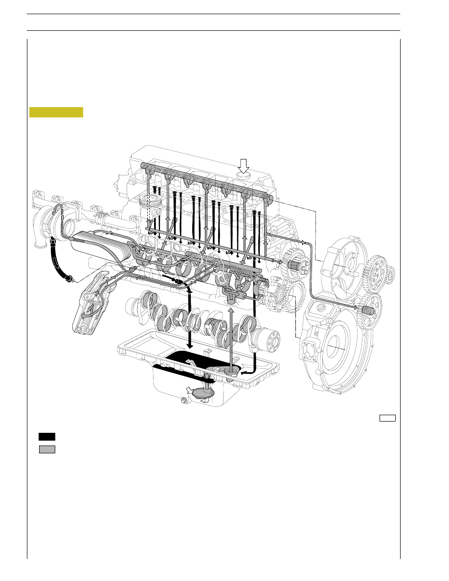
LUBRICATION
Engine lubrication is obtained with a gear pump driven by the crankshaft via gears.
A heat exchanger governs the temperature of the lubricating oil.
The oil filter, signalling sensors and safety valves are installed in the intercooler.
114244
Figure 1
(Demonstration)
LUBRICATION DIAGRAM
Dropping oil
Pressure oil
4
SECTION 1 - GENERAL SPECIFICATIONS
CURSOR ENGINES G-DRIVE
Base - June 2007
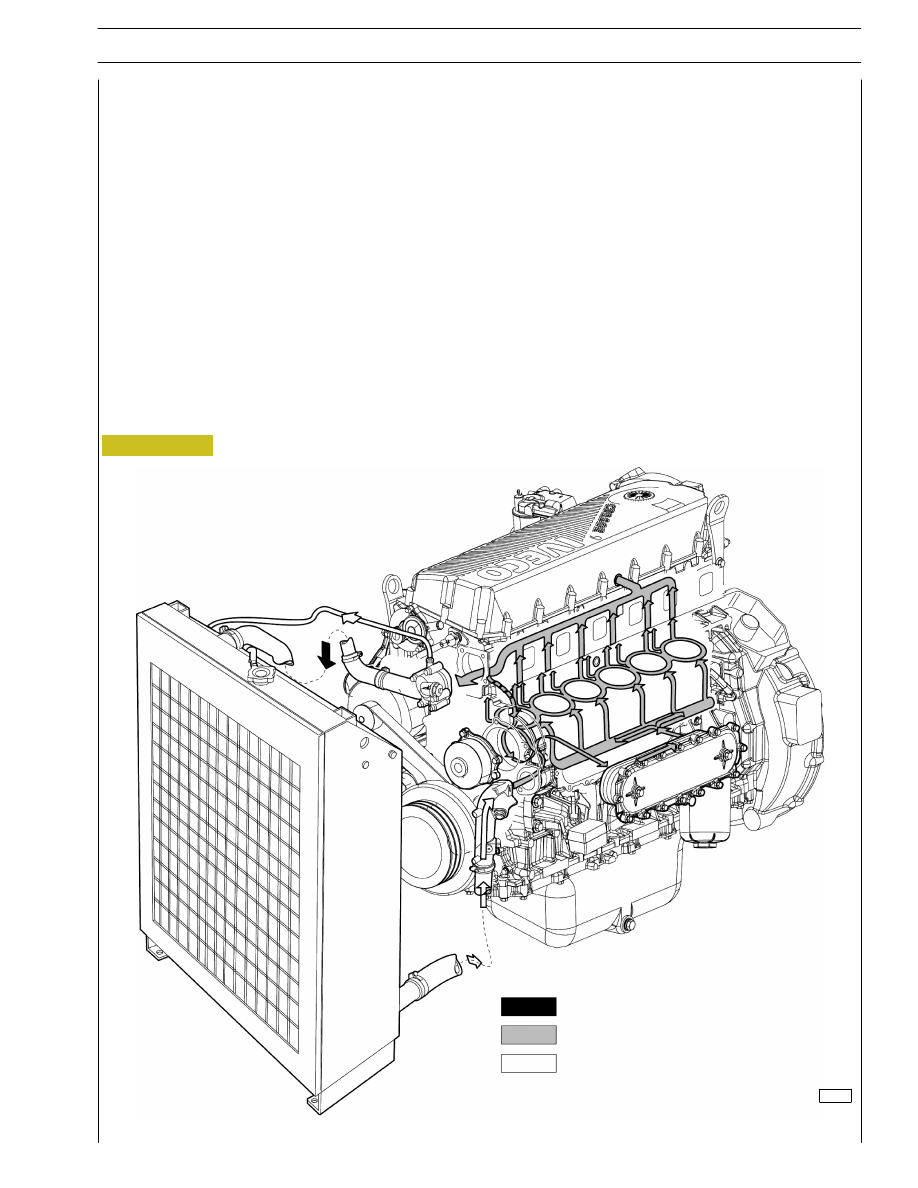
COOLING
Description
The engine cooling system is of the closed-circuit, forced circulation type.
It consists mainly of the following components:
- expansion tank,
- a heat exchanger to cool down lubrication oil;
- a water pump with centrifugal system incorporated in the cylinder block;
- fan;
- a 2-way thermostat controlling the coolant circulation.
Operation
The water pump is actuated by the crankshaft through a poli-V belt and sends coolant to the cylinder block, especially to the cylinder
head (bigger quantity). When the coolant temperature reaches and overcomes the operating temperature, the thermostat is
opened and from here the coolant flows into the radiator and is cooled down by the fan.
Figure 2
119978
Water flowing out of the thermostat
Water circulating in the engine Water
flowing into the pump
COOLING SYSTEM DIAGRAM
5
CURSOR ENGINES G-DRIVE
SECTION 1 - GENERAL SPECIFICATIONS
Base - June 2007

Figure 3
119979
SUPPLY
The Common Rail supply system is equipped with a special pump that maintains fuel at constant high pressure regardless from
phase and cylinder under injection and accumulated in an common duct shared by all electric injectors.
Therefore, fuel at injection pressure, calculated by ECU, is always available at electric injection inlet.
When the solenoid valve of an injector is energized by ECU, in related cylinder the injection of fuel taken directly from the
rail takes place.
Return
circuit
Supply
circuit
6
SECTION 1 - GENERAL SPECIFICATIONS
CURSOR ENGINES G-DRIVE
Base - June 2007
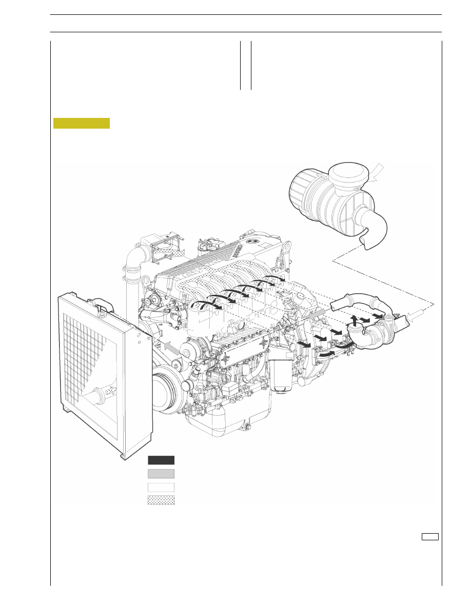
TURBOCHARGING
The turbocharging system consists of:
- air filter;
- Turbocharger.
Figure 4
SUPERCHARGING SYSTEM DIAGRAM
Engine exhaust gas
Intake air
Inlet
Exhaust
119980
7
CURSOR ENGINES G-DRIVE
SECTION 1 - GENERAL SPECIFICATIONS
Base - June 2007
Нет комментариевНе стесняйтесь поделиться с нами вашим ценным мнением.
Текст