Engines Iveco C87 / Cursor 87. Manual — part 24
115882
Figure 1
Figure 2
Figure 3
Figure 4
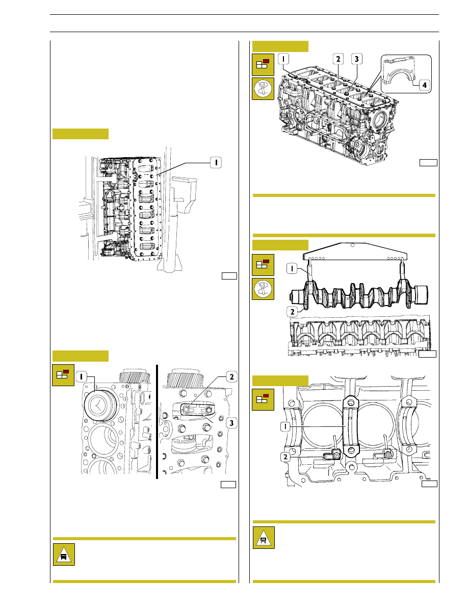
Untighten screws (2) fixing the connecting rod cap (3) and
remove it. Remove the connecting rod-piston (1) assembly
from the upper side.
Repeat these operations for the other pistons.
Use adequate hexagonal spanner, unlock screws (1 and 3)
and remove stiffening plate (2) as well as main journals (4).
115881
Rotate the block (1) to the vertical position.
Using tool 99360500 (1), remove the crankshaft (2).
Remove the main bearing shells (1), unscrew the screws and
take out the oil nozzles (2).
Remove the cylinder liners as described under the relevant
subheading on page 15.
After disassembling the engine, thoroughly clean
disassembled parts and check their integrity.
Instructions for main checks and measures are given
in the following pages, in order to determine
whether the parts can be re-used.
Keep the big end bearing shells in their respective
housings and/or note down their assembly position
since, if reusing them, they will need to be fitted in
the position found upon removal.
Note down the assembly position of the top and
bottom main bearing shells since, if reusing them, they
will need to be fitted in the position found upon
removal.
ENGINE OVERHAUL
ENGINE REMOVAL AT THE BENCH
The
following
instructions
are
prescribed
on
the
understanding that the engine has previously been placed on
the rotating bench and that removal of all specific
components of the equipment have been already removed
as well. (See Section 3 of the manual herein).
The section illustrates therefore all the most important
engine overhaul procedures.
47571
114615
NOTE
Figure 5
114035
SECTION 4 - OVERHAUL AND TECHNICAL SPECIFICATIONS
11
F2C CURSOR ENGINES
A = Selection class
∅ 117 — 117.012 mm
B = Selection class
∅ 117.010 — 117.022 mm
X = Selection class marking area
In case of maximum wear >0.150 mm or maximum
ovalization >0.100 mm compared to the values indicated in
the figure, the liners must be replaced as they cannot be
ground, lapped or trued.
REPAIR OPERATIONS
CYLINDER BLOCK
Checks and measurements
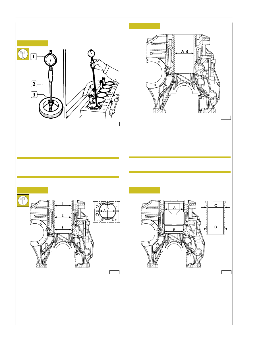
Internal diameter of the cylinder liners is checked for
ovalization, taper and wear, using a bore dial (1) centesimal
gauge 99395687 (2) previously reset to ring gauge (3),
diameter 117 mm.
If dia.117 mm ring gage is not available, use a
micrometer.
34994
225036
114037
Figure 6
Figure 7
Figure 8
Figure 9
1 = 1
st
measuring
2 = 2
nd
measuring
3 = 3
rd
measuring
Carry out measurings on each cylinder liner at three different
levels and on two (A-B) surfaces, to one another
perpendicular, as shown in Figure.
(Demonstration)
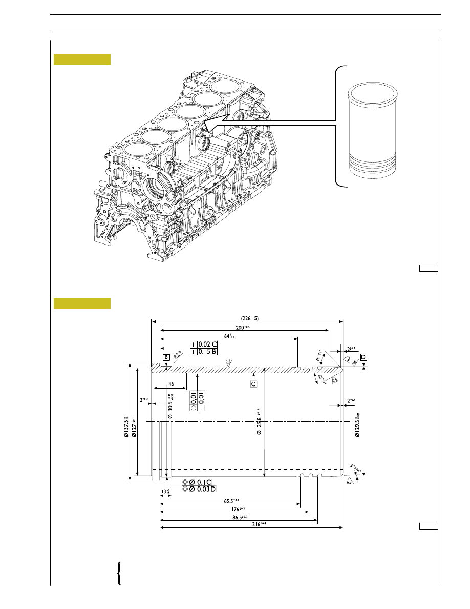
Cylinder liners are equipped with spare parts with
“A“ selection class.
114035
NOTE
NOTE
A = Ø 130.500 to 130.525 mm
B = Ø 129.510 to 129.535 mm
C = Ø 130.461 to 130.486
D = Ø 129.475 to 129.500 mm
The figure shows the outer diameters of the cylinder liners
and the relative seat inner diameters.
The cylinder liners can be extracted and installed several
times in different seats, if necessary.
12
SECTION 4 - OVERHAUL AND TECHNICAL SPECIFICATIONS
F2C CURSOR ENGINES
Base - June 2007
114038
Figure 10
Figure 11
CYLINDER LINERS MAIN DATA
CYLINDER BLOCK ASSEMBLY WITH CHROME-PLATED CYLINDER LINERS
A mm 117.000 to 117.012
B mm 117.010 to 117.022
Selection class
CYLINDER LINERS
114039
SECTION 4 - OVERHAUL AND TECHNICAL SPECIFICATIONS
13
F2C CURSOR ENGINES
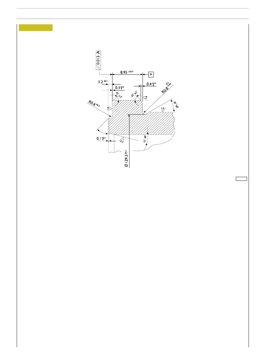
DETAIL “X”
“A“ = Selection class marking area
Figure 12
114040
14
SECTION 4 - OVERHAUL AND TECHNICAL SPECIFICATIONS
F2C CURSOR ENGINES
Base - June 2007
Нет комментариевНе стесняйтесь поделиться с нами вашим ценным мнением.
Текст