Engines Iveco C87 / Cursor 87. Manual — part 2
GENERAL WARNINGS ON THE ELECTRIC SYSTEM
To start up the engine, do not use fast chargers. Start up must only be performed with either separate batteries or special
truck.
A wrong polarisation of supply voltage in drive electronic central units (for instance, a wrong polarisation of batteries)
can cause them to be destroyed.
Disconnect the batteries from the system during their recharging with an external apparatus.
On connecting, only screw up connector (temperature sensors, pressure sensors etc.) nuts at prescribed tightening
torque.
Before disconnecting the junction connector from an electronic central unit, isolate the system.
Do not directly supply electronic central units servo components at nominal vehicle voltage.
Cables must be arranged such as to result to be parallel to reference plane, i.e. as close as possible to chassis/body
structure.
Once the intervention on the electric system has been completed, recover connectors and wiring harnesses according
to original arrangement.
If an intervention has to be made on the electric/electronic system, disconnect batteries from the system; in this case,
always disconnect, as a first one, the chassis bonding cable from batteries negative terminal.
Before connecting the batteries to the system, make sure that the system is well isolated.
Disconnect the external recharging apparatus from the public utility network before taking apparatus pins off battery
terminals.
Do not cause sparks to be generated in checking if the circuit is energised.
Do not use a test lamp in checking circuit continuity, but only use proper control apparatuses.
Make sure that the electronic devices wiring harnesses (length, lead type, location, strapping, connection to screening
braiding, bonding, etc.) comply with FPT system and are carefully recovered after repair or maintenance interventions.
Measurements in drive electronic central units, plugged connections and electric connections to components can only
be made on proper testing lines with special plugs and plug bushes. Never use improper means like wires, screwdrivers,
clips and the like in order to avoid the danger of causing a short circuit, as well as of damaging plugged connections, which
would later cause contact problems.
Connectors present must be seen from cable side. Connectors views contained in the manual are representative of cable
side.
!
NOTE
INTRODUCTION
7
F2C CURSOR ENGINES
8
INTRODUCTION
F2C CURSOR ENGINES
Base - June 2007
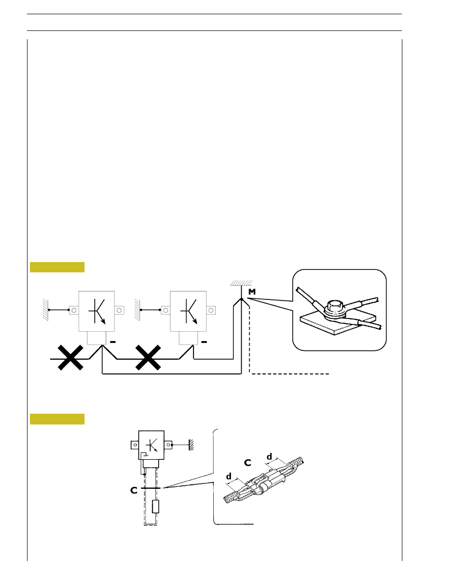
Negative leads connected to a system bonded point must be both as short and possible and “star“-connected to each other, trying
then to have their centering tidily and properly made (Figure 1, re. M).
Further, following warnings are to be compulsorily observed for electronic components:
-
Electronic central units must be connected to system bonding when they are provided with a metallic shell.
-
Electronic central units negative cables must be connected both to a system bonding point such as the dashboard opening
bonding (avoiding “serial“ or “chain“ connections), and to battery negative terminal.
-
Analog bonding (sensors), although not connected to battery negative system/terminal bonding, must have optimal isolation.
Consequently, particularly considered must be parasitic resistances in lugs: oxidising, clinching defects, etc.
-
Screened circuits braiding must only electrically contact the end towards the central unit entered by the signal (Figure 2).
-
If junction connectors are present, unscreened section d, near them, must be as short as possible (Figure 2).
-
Cables must be arranged such as to result to be parallel to reference plane, i.e. as close as possible to chassis/body structure.
1.
NEGATIVE CABLES
“
STAR
“
CONNECTION TO SYSTEM BONDING M
2.
SCREENING THROUGH METALLIC BRAIDING OF A CABLE TO AN ELECTRONIC COMPONENT — C. CONNECTOR
d. DISTANCE ! 0
88039
Figure 1
Figure 2
INTRODUCTION
9
F2C CURSOR ENGINES
OPTIONAL ELECTRICAL AND MECHANICAL PARTS INSTALLATIONS
Assemblies shall be modified and equipped with additions - and their accessories shall be fitted - in accordance with the assembling
directives issued.
It is reminded that, especially about the electric system, several electric sockets are provided for as series (or optional) sockets in
order to simplify and normalise the electrical intervention that is care of preparation personnel.
It is absolutely forbidden to make modifications or connections to electric central units wiring harnesses; in particular,
the data interconnection line between central units (CAN line) is to be considered inviolable.
CONVERSIONS
BETWEEN
THE
MAIN
UNITS
OF
MEASUREMENT
OF
THE
INTERNATIONAL SYSTEM AND MOST USED DERIVED QUANTITIES
Power
1 kW
=
1.36 metric HP
1 kW
=
1.34 HP
1 metric HP =
0.736 kW
1 metric HP =
0.986 HP
1 HP
=
0.746 kW
1 HP
=
1.014 metric HP
Torque
1 Nm
=
0.1019 kgm
1 kgm
=
9.81 Nm
Revolutions per time unit
1 rad/s
=
1 rpm x 0.1046
1 rpm
=
1 rad/s x 9.5602
Pressure
1 bar
=
1.02 kg/cm
2
1 kg/cm
2
=
0.981 bar
1 bar
=
10
5
Pa
Where accuracy is not particularly needed:
- Nm unit is for the sake of simplicity converted into kgm according to ratio 10:1
1 kgm
=
10 Nm;
- bar unit is for the sake of simplicity converted into kg/cm
2
according to ratio 1:1
1 kg/cm
2
=
1 bar.
Temperature
0
° C = 32° F
1
° C = (1 x 1.8 + 32) ° F
10
INTRODUCTION
F2C CURSOR ENGINES
Base - June 2007
vehicle
Section
title
Page
number
Printout
number
Language
Publication
Basic edition referred to
month - year editorial
phase closing
When month - year update
is present (revi) to the basic
edition
KEY OF LECTURE OF THE HEADINGS AND FOOTNOTES
Нет комментариевНе стесняйтесь поделиться с нами вашим ценным мнением.
Текст