Engines Iveco N45, N67. Manual — part 24
SECTION 4 - OVERHAUL AND TECHNICAL SPECIFICATIONS
9
F4HE NEF ENGINES
Print P2D32N003GB
Base - February 2006
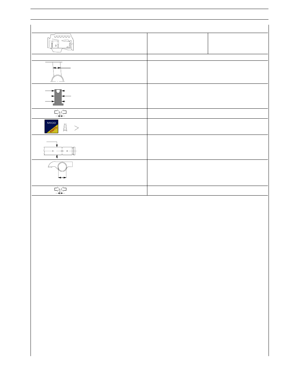
Type
4 CYLINDERS
6 CYLINDERS
CYLINDER HEAD — TIMING SYSTEM
mm
∅ 1
Tappet cap housing
on block
∅ 1
16.000 to 16.030
∅ 2
3
∅
∅
2
Tappet cap outside
diameter:
∅ 2
∅ 3
15.924 to 15.954
15.960 to 15.975
Between tappets and housings
0.025 to 0.070
Tappets
-
∅ 1
Rocker shaft
∅ 1
21.965 to 21.977
∅ 2
Rockers
∅ 2
22.001 to 22.027
Between rockers and shaft
0.024 to 0.162

70159
70158
70160
70161
70162
Figure 1
Figure 2
Figure 3
Figure 4
Loosen the fixing screws (1) and remove the rod caps (2).
Withdraw the pistons including the connecting rods from the
top of the engine block.
Remove the screws (1) and the main bearing caps (2).
The second last main bearing cap (1) and the relevant support
are fitted with shoulder half-bearing (2).
Use tool 99360500 (1) and hoist to remove the crankshaft (2)
from the block.
Remove the main half-bearings (1).
Remove the screws (2) and remove the oil nozzles (3).
!
Keep the half-bearings into their housings since in case
of use they shall be fitted in the same position found
at removal.
!
Take note of lower and upper half-bearing assembling
positions since in case of reuse they shall be fitted in
the same position found at removal.
Figure 5
4 AND 6 ENGINE OVERHAUL
ENGINE REMOVAL AT THE BENCH
The following instructions assume that the engine has
previously been placed on the rotating bench and that
removal of all specific components of the Iveco Motors
equipment have been already removed as well. (See Section
3 of the manual herein).
The section illustrates therefore all the most important engine
overhaul procedures.
The following operations are relating to the 4 cylinder engine
but are similar and applicable for the 6 cylinder.
SECTION 4 - OVERHAUL AND TECHNICAL SPECIFICATIONS
11
F4HE NEF ENGINES
Print P2D32N003GB
Base - February 2006
70163
70165
70164
70166
70167
Figure 6
Figure 7
Figure 8
Figure 9
Figure 10
Remove the screws (1) and disconnect camshaft (3) retaining
plate (2).
Withdraw carefully the camshaft (1) from the engine block.
Withdraw the tappets (1) from the engine block.
Once
engine
is
disassembled,
clean
accurately
the
cylinder-block assembly.
Use the proper rings to handle the cylinder unit.
The engine block shall not show cracks.
Check operating plug conditions and replace them in case of
uncertain seal or if rusted.
Inspect cylinder barrel surfaces; they shall be free from seizing,
scores, ovalisation, taper or excessive wear.
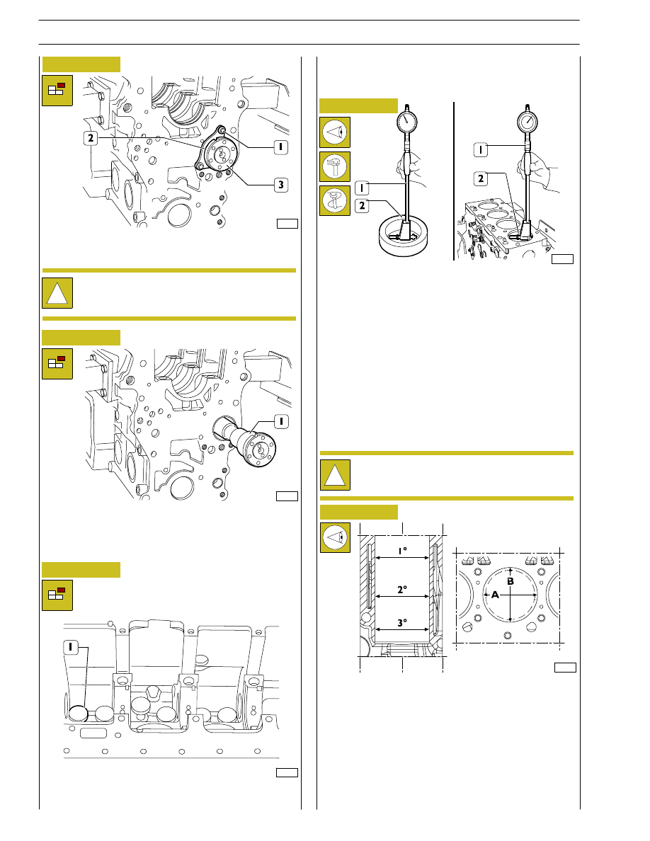
Inspection of cylinder barrel bore to check ovalisation, taper
and wear shall be performed using the bore dial gauge (1)
fitted with the dial gauge previously set to zero on the ring
gauge (2) of the cylinder barrel diameter.
Measurements shall be performed on each cylinder, at three
different heights in the barrel and on two planes perpendicular
with each other: one parallel to the longitudinal axis of the
engine (A), and the other perpendicular (B). Maximum wear
is usually found on plane (B) in correspondence with the first
measurement.
Should ovalisation, taper or wear be found, bore and grind the
cylinder barrels. Cylinder barrel regrinding shall be performed
according to the spare piston diameter oversized by 0.5 mm
and to the specified assembling clearance.
!
Take note of plate (2) assembling position.
REPAIR OPERATIONS
CYLINDER UNIT
Checks and measurements
!
Should the ring gauge be not available, use a
micrometer for zero-setting.
s
12
SECTION 4 - OVERHAUL AND TECHNICAL SPECIFICATIONS
F4HE NEF ENGINES
Base - February 2006
Print P2D32N00GB
zs
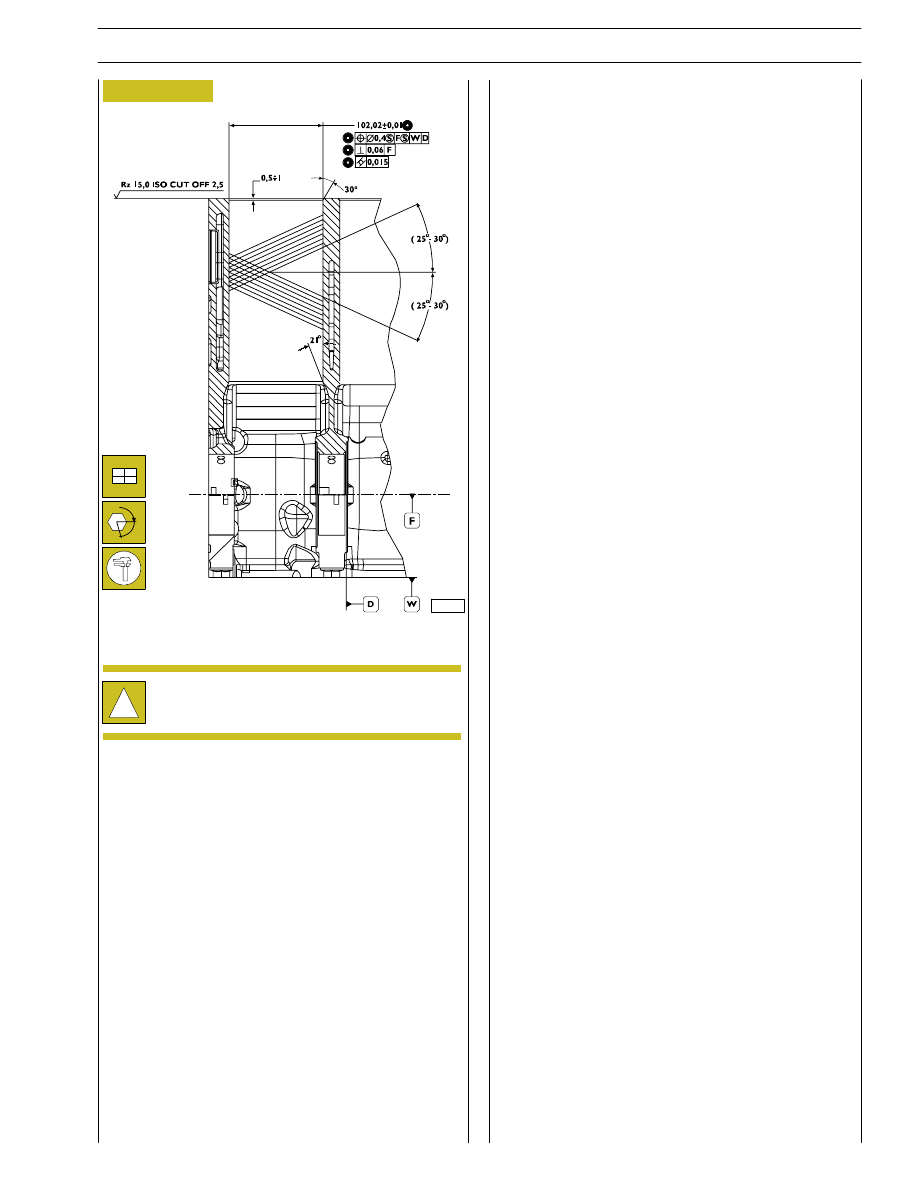
Figure 11
!
In case of regrinding, all barrels shall have the same
oversize (0.5 mm).
Checking head supporting surface on cylinder
unit
When finding the distortion areas, replace the cylinder unit.
Planarity error shall not exceed 0.075 mm.
Check cylinder unit operating plug conditions, replace them
in case of uncertain seal or if rusted.
α
Check main bearing housings as follows:
- fit the main bearings caps on the supports without
bearings;
- tighten the fastening screws to the specified torque;
- use the proper internal gauge to check whether the
housing diameter is falling within the specified value.
Replace if higher value is found.
107267
SECTION 4 - OVERHAUL AND TECHNICAL SPECIFICATIONS
13
F4HE NEF ENGINES
Print P2D32N003GB
Base - February 2006
Нет комментариевНе стесняйтесь поделиться с нами вашим ценным мнением.
Текст