Engine Iveco C10/C13/C78/Cursor 13/Cursor 78. Manual — part 120
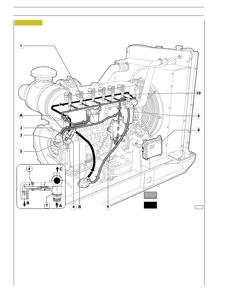
Figure 16
112861
F3B ENGINE FEED SCHEME
1. Fuel filter - 2. Valve, to recirculate fuel from injectors, integrated in feed pump (start of opening at 3.5 bar) - 3. Feed pump
- 4. Overpressure valve to return fuel to tank (start of opening at 0.2 bar) - 5. Pressure control valve (start of opening at 5
bar) - 6. Fuel pre-filter with priming pump - 7. Fitting - 8. Central unit - 9. Heat exchanger- 10. Pump injectors
A. Fuel arriving at injectors - B. Fuel returning to tank - C. Fuel entering from injectors into feed pump
Delivery circuit
Return circuit
16
SECTION 1 - GENERAL SPECIFICATIONS
92830
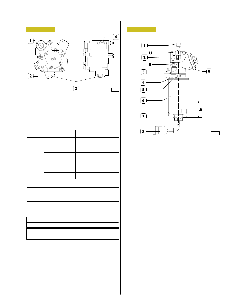
Engine feed pump
1. Overpressure valve - 2. Pressure control valve -
3. Sucking in fuel - 4. Delivering fuel to injectors.
Pump performances
Pump rotation speed
(rpm)
Minimum flow rate
(l/h)
2600
310
600
45
170
12
100
Test
conditions
Negative pressure
on aspiration
(bar)
Pressure on delivery
(bar)
Test liquid
temperature
(˚C)
Test liquid
0.5
5
30
0.3
3
30
0.3
0,3
30
0.3
0.3
30
ISO 4113
Field of use
Pump rotation speed
(rpm)
Overrunning rotation speed (max 5 min)
(rpm)
Diesel oil temperature
(˚C)
Filtering rate on aspiration
(micron)
Negative pressure on aspiration (bar)
2600
4100 max
-25/+80
30
0.5 max
Pressure control valve
Valve calibration
5
÷ 5.8
Injectors return valve
Valve calibration
3.2
÷ 3.8
F2B engine fuel supply pump
Figure 17
Figure 18
Heated sedimentation tank prefilter
107885
1. Thermostat - 2. Support - 3. Air bleed screw -
4. Heater - 5. Heater connector - 6. Water separation
cartridge - 7. Water present indication sensor -
8. Connector - 9. Priming pump -
A. Water accumulation capacity- E. Fuel entry -
U. Fuel exit .
Characteristics
Water accumulation capacity
∼ 270 ml
Thermostat:
-
opening temperature
+5
± 3 °C
-
closing temperature
-3
± 3 °C
Tightening torque
Bleed screw locking (3)
7
± 1 Nm
Cartridge locking (6)
18
± 2 Nm
Locking water present indicator sensor
0.8
± 0.1 Nm
SECTION 1 - GENERAL SPECIFICATIONS
17
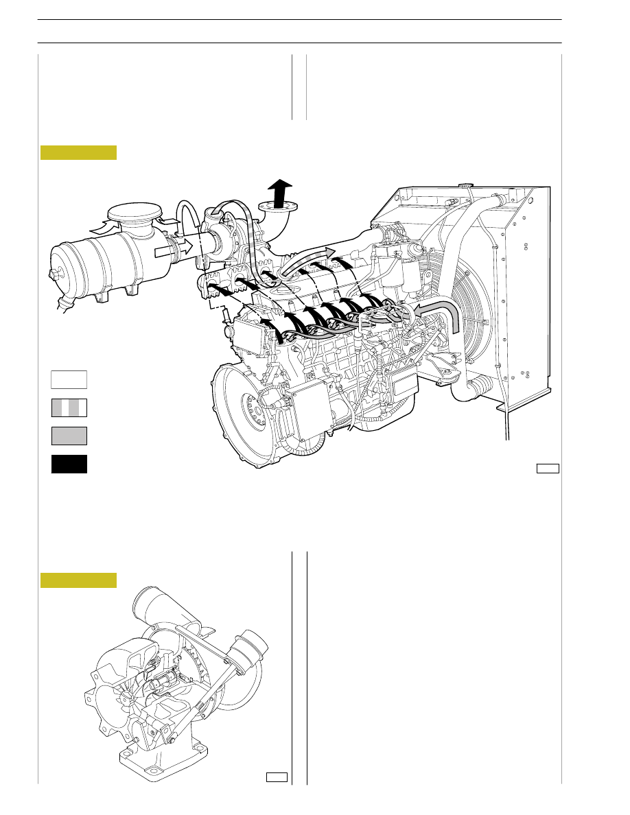
Figure 19
TURBOCHARGING
The turbocharging system consists of:
- air filter;
- Wastegate turbocharger.
HX 40W turbocompressor
The turbocompressor is a turbocompressor with a return
valve.
It is mainly composed by:
- a central unit where a shaft is positioned supported by
bushings, a turbine rotor and a compressor rotor are
mounted on each end;
- a turbine unit and a compressor unit mounted at the end
of the central unit;
- return valve applied on the turbine unit. It divides burnt
gases outlet, sending one part directly to the outlet tube
when the boost of the compressor reaches the setting
value.
71766
F2B engine
107901
Intake air
Compressed air (hot)
Compressed air (cooled)
Exhaust
Figure 20
F2B ENGINE SUPERCHARGING SYSTEM DIAGRAM
18
SECTION 1 - GENERAL SPECIFICATIONS

Figure 21
HX 60W turbocompressor
The turbocompressor is a turbocompressor with a return
valve.
It is mainly composed by:
- a central unit where a shaft is positioned supported by
bushings, a turbine rotor and a compressor rotor are
mounted on each end;
- a turbine unit and a compressor unit mounted at the end
of the central unit;
- return valve applied on the turbine unit. It divides burnt
gases outlet, sending one part directly to the outlet tube
when the boost of the compressor reaches the setting
value.
71766
F3B engine
107897
Figure 22
F3B ENGINE SUPERCHARGING SYSTEM DIAGRAM
Engine exhaust gas
Intake air
A = Inlet
S = Exhaust
SECTION 1 - GENERAL SPECIFICATIONS
19
Нет комментариевНе стесняйтесь поделиться с нами вашим ценным мнением.
Текст