Engine Iveco C10/C13/C78/Cursor 13/Cursor 78. Manual — part 6

Figure 1
92828
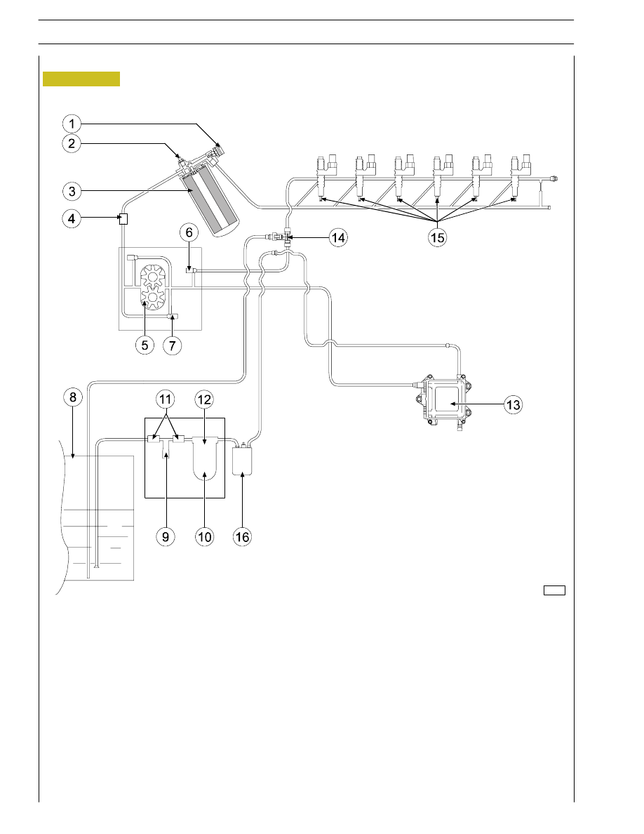
FUEL FEED
Fuel feed is obtained by means of a pump, fuel filter and
pre-filter, 6 pump-injectors controlled by the camshaft by
means of rockers and by the electronic control unit.
Return circuit
Delivery circuit
ENGINE FUEL SUPPLY DIAGRAM WITH FUEL PUMP ON THE TIMING SYSTEM CONTROL
1. Fuel filter - 2. Valve for fuel recirculation from injectors integrated in the fuel pump (start opening 3,5 bar) - 3. Fuel pump
- 4. Overpressure valve for fuel return to the tank (start opening 0,2 bar) - 5. Pressure control valve (start opening 5 bar) -
6. Prefilter with priming pump - 7. Connector - 8. Gearcase - 9. Heat exchanger - 10. Pump injectors.
A. Fuel arrival from injectors - B. Fuel return to the tank - C. Fuel inlet from injectors in the fuel filter
SECTION 2 - FUEL
3
81817
Figure 2
1. Temperature sensor - 2. Bleed valve - 3. Secondary fuel filter - 4. By-pass valve (0.3
÷ 0.4 bar) - 5. Fuel supply pump -
6. Integrated valve (3.5 bar) - 7. Pressure relief valve (5 bar) - 8. Fuel tank - 9. Priming pump - 10. Primary fuel filter -
11. Check valve (opening 0.1 bar) - 12. Heater - 13. Electronic control unit - 14. Fuel return union with valve built in
(0.2 bar) - 15. Pump-injectors - 16. Electric fuel pump.
FUEL SUPPLY DIAGRAM
4
SECTION 2 - FUEL
73547
44908
98870
Figure 3
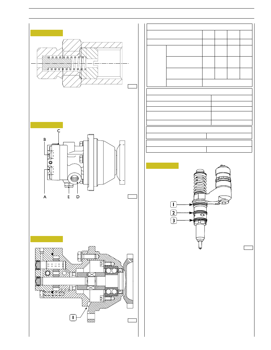
Fuel pump mounted on timing system
A. Fuel inlet — B. Fuel delivery — C. By-pass nut —
D. Fuel return from the pump-injectors —
E. Pressure relief valve — Opening pressure: 5-8 bars.
CROSS-SECTION OF THE FUEL PUMP
1. Oil and fuel leakage indicator.
1. Fuel/oil seal — 2. Fuel/diesel seal — 3. Fuel/exhaust gas seal.
The injector-pump is composed of: pumping element, nozzle,
solenoid valve.
Fuel pump
Figure 4
Figure 5
Injector-pump
Figure 6
92829
An overpressure valve is a single-acting valve, calibrated to 0.2
÷ 0.3 bar, placed on the piping that returns fuel to tank. The
overpressure valve prevents fuel duct in cylinder head from
emptying with engine stopped.
Overpressure valve
Pump performances
Pump rotation speed
(rpm)
Minimum flow rate
(l/h)
4100
310
900
45
250
12
140
6
Test
conditions
Negative pressure
on aspiration
(bar)
Pressure on delivery
(bar)
Test liquid
temperature
(˚C)
Test liquid
0.5
5
30
0.3
3
30
0.3
0,3
30
0.3
0.3
20
ISO 4113
Field of use
Pump rotation speed
(rpm)
Overrunning rotation speed (max 5 min) (rpm)
Diesel oil temperature
(˚C)
Filtering rate on aspiration
(micron)
Negative pressure on aspiration (bar)
2600
4100 max
-25/+80
30
0.5 max
Pressure control valve
Valve calibration
5
÷ 5.8
Injectors return valve
Valve calibration
3.2
÷ 3.8
Pumping element
The pumping element is operated by a rocker arm governed
directly by the cam of the camshaft.
The pumping element is able to ensure a high delivery
pressure. The return stroke is made by means of a return
spring.
Nozzle
Garages are authorized to perform fault diagnosis solely on
the entire injection system and may not work inside the
injector-pump, which must only be replaced.
SECTION 2 - FUEL
5
0 411 700 002
XXXXXX XXXX X
868 USA /
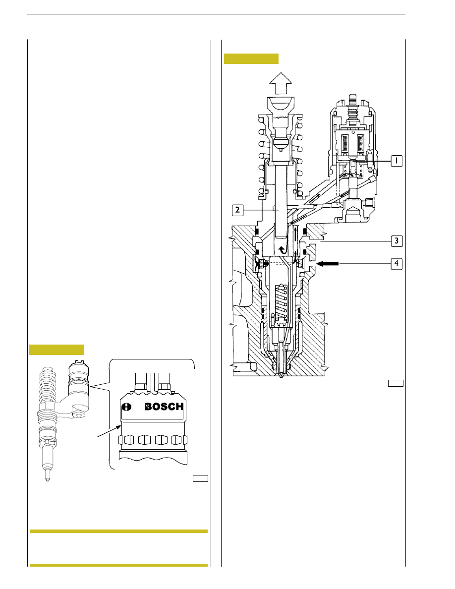
1. Fuel valve - 2. Pumping element - 3. Fuel outlet -
4. Filling and backflow passage.
87060
60669
Figure 7
For each replaced injector you shall connect with the
diagnosis device and when it is required by the program you
shall insert the printed code on the injector (
→
)
to program
the gearcase again.
Injector Phases
When checking the clearance of the rocker arms,
it is important to check the injector-pump
pre-load.
Filling phase
During the filling phase the pumping element (2) runs up to
the top position.
After passing the highest point of the cam, the rocker arm
roller comes near the base ring of the cam.
The fuel valve (1) is open and fuel can flow into the injector
via the bottom passage (4) of the cylinder head.
Filling continues until the pumping element reaches its top
limit.
Figure 8
NOTE
A specific fault-diagnosis program, included in the control
unit, is able to check the operation of each injector (it
deactivates one at a time and checks the delivery of the other
five).
Fault diagnosis makes it possible to distinguish errors of an
electrical origin from ones of a mechanical/hydraulic origin.
It indicates broken pump-injectors.
It is therefore necessary to interpret all the control unit error
messages correctly.
Any defects in the injectors are to be resolved by replacing
them.
Solenoid valve
The solenoid, which is energized at each active phase of the
cycle, via a signal from the control unit, controls a slide valve
that shuts off the pumping element delivery pipe.
When the solenoid is not energized, the valve is open, the
fuel is pumped but it flows back into the return pipe with the
normal transfer pressure of approximately 5 bars.
When the solenoid is energized, the valve shuts and the fuel,
not being able to flow back into the return pipe, is pumped
into the nozzle at high pressure, causing the needle to lift.
The amount of fuel injected depends on the length of time
the slide valve is closed and therefore on the time for which
the solenoid is energized.
The solenoid valve is joined to the injector body and cannot
be removed.
On the top there are two screws securing the electrical
wiring from the control unit.
To ensure signal transmission, tighten the screws with a torque
wrench to a torque of 1.36 — 1.92 Nm (0.136 — 0.192 kgm).
6
SECTION 2 - FUEL
Нет комментариевНе стесняйтесь поделиться с нами вашим ценным мнением.
Текст