Engine Iveco C10/C13/C78/Cursor 13/Cursor 78. Manual — part 105
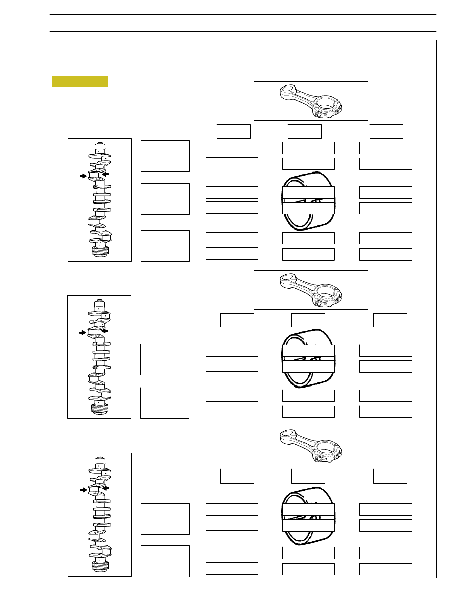
Figure 31
green/black
Selecting big end bearing shells (ground journals)
If the journals have been ground, the procedure described so far cannot be applied.
In this case, it is necessary to check (for each of the undersizings) which field of tolerance includes the new diameter of the
crankpins and to mount the bearing shells identified with the relevant table.
-0.127
1
2
3
89.843
89.852
green/black
green/black
green/black
green/black
green/black
green/black
red/black
red/black
green/black
green/black
green/black
red/black
red/black
red/black
red/black
green/black
green/black
89.853
89.862
89.863
89.873
1
2
3
red/black =
2.028 to 2.038 mm
green/black =
2.039 to 2.048 mm
-0.254
1
2
3
89.726
89.735
red
green
green
red
green
green
red
=
2.092 to 2.102 mm
green =
2.103 to 2.112 mm
-0.508
1
2
3
89.472
89.481
red
green
green
red
green
green
red
red
green
red
red
green
89.482
89.492
red
red
green
red
red
green
red
=
2.219 to 2.229 mm
green =
2.230 to 2.239 mm
89.736
89.746
SECTION 4 - OVERHAUL AND TECHNICAL SPECIFICATIONS
25
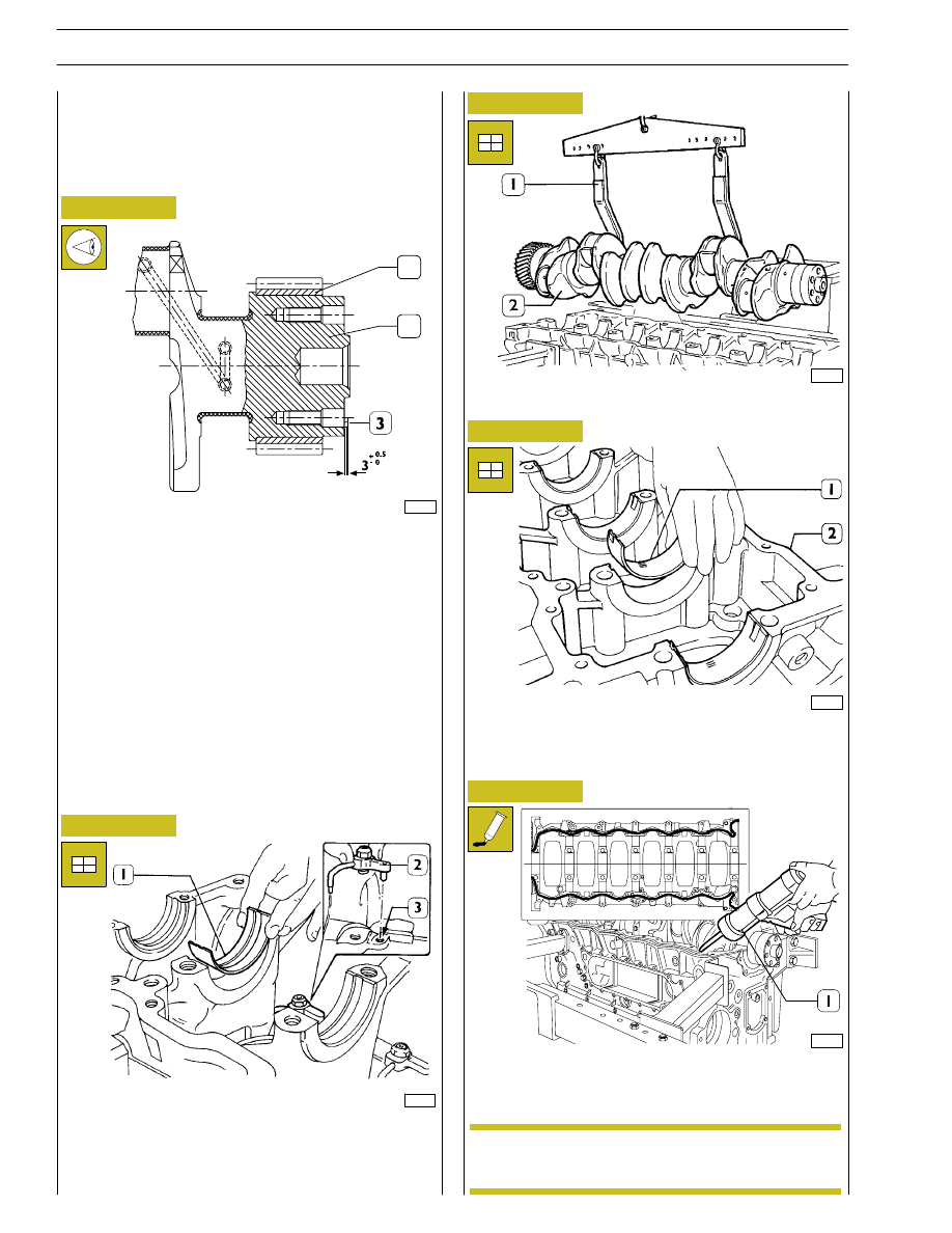
Install the half-bearings (1) on the main bearings in the
underblock (2).
Check the installation clearance between the main journals
and the relative bearings as follows:
Using the hoist and hook 99360500 (1) mount the driving
shaft (2).
When fitting gear (1) onto drive shaft (2), the gear must be
heated for 2 hours max. in a furnace, at a temperature not
higher than 180
°C.
Let them cool down after the installation.
If changing the pin (3), after fitting it on, check it protrudes
from the crankshaft as shown in the figure.
49020
47579
47578
49021
Figure 32
Figure 33
Figure 34
Figure 35
Install the oil spray nozzles (2) and have the dowel coincide
with the block hole (3).
Install the half-bearings (1) on the main bearings.
Replacing the timing control gear and the oil
pump
Check that the teeth of the gears are not damaged or worn,
otherwise remove them using the appropriate extractor.
Checking main journal installation clearance
1
2
Figure 36
By means of suitable equipment (1) apply silicone LOCTITE
5970 to the block, as shown in the figure.
Frame shows the application scheme for the LOCTITE 5970
sealant.
101507
Fit the underblock within 10’ of the application of
the sealant.
NOTE
26
SECTION 4 - OVERHAUL AND TECHNICAL SPECIFICATIONS
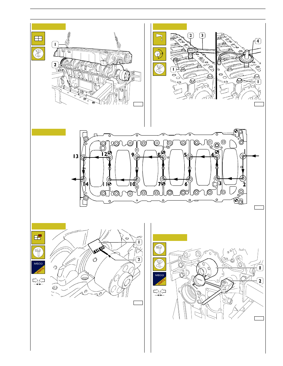
- Lubricate the internal screws (1) with UTDM oil and
tighten them with a torque wrench (3) to a torque of
120 Nm, using tool 99395216 (4), to an angle of 60
°,
following the diagram below.
Set two journals of the crankshaft (2) parallel to the
longitudinal axis, a section of calibrated wire. Using
appropriate hooks and tackle, mount the crankcase base (1).
60559
47579
47578
47588
60593
Figure 37
Figure 38
Figure 39
Figure 40
Figure 41
- Remove the crankcase base.
The clearance between the main bearings and their journals
is measured by comparing the width taken on by the
calibrated wire (2) at the point of greatest crushing with the
graduated scale on the case (1) containing the calibrated
wire.
The numbers on the scale give the clearance of the coupling
in millimetres. If you find the clearance is not as required,
replace the bearing shells and repeat the check.
FRONT SIDE
DIAGRAM OF SEQUENCE FOR TIGHTENING THE SCREWS FIXING
THE BOTTOM CRANKCASE BASE TO THE CRANKCASE
Checking crankshaft end float
α
The end float is checked by setting a dial gauge (1) 99395603
with a magnetic base on the crankshaft (2) as shown in the
figure. If you find the clearance to be greater than as required,
replace the rear main bearing shells carrying the thrust
bearings and repeat the clearance check.
SECTION 4 - OVERHAUL AND TECHNICAL SPECIFICATIONS
27
47595
47596
Figure 42
Figure 43
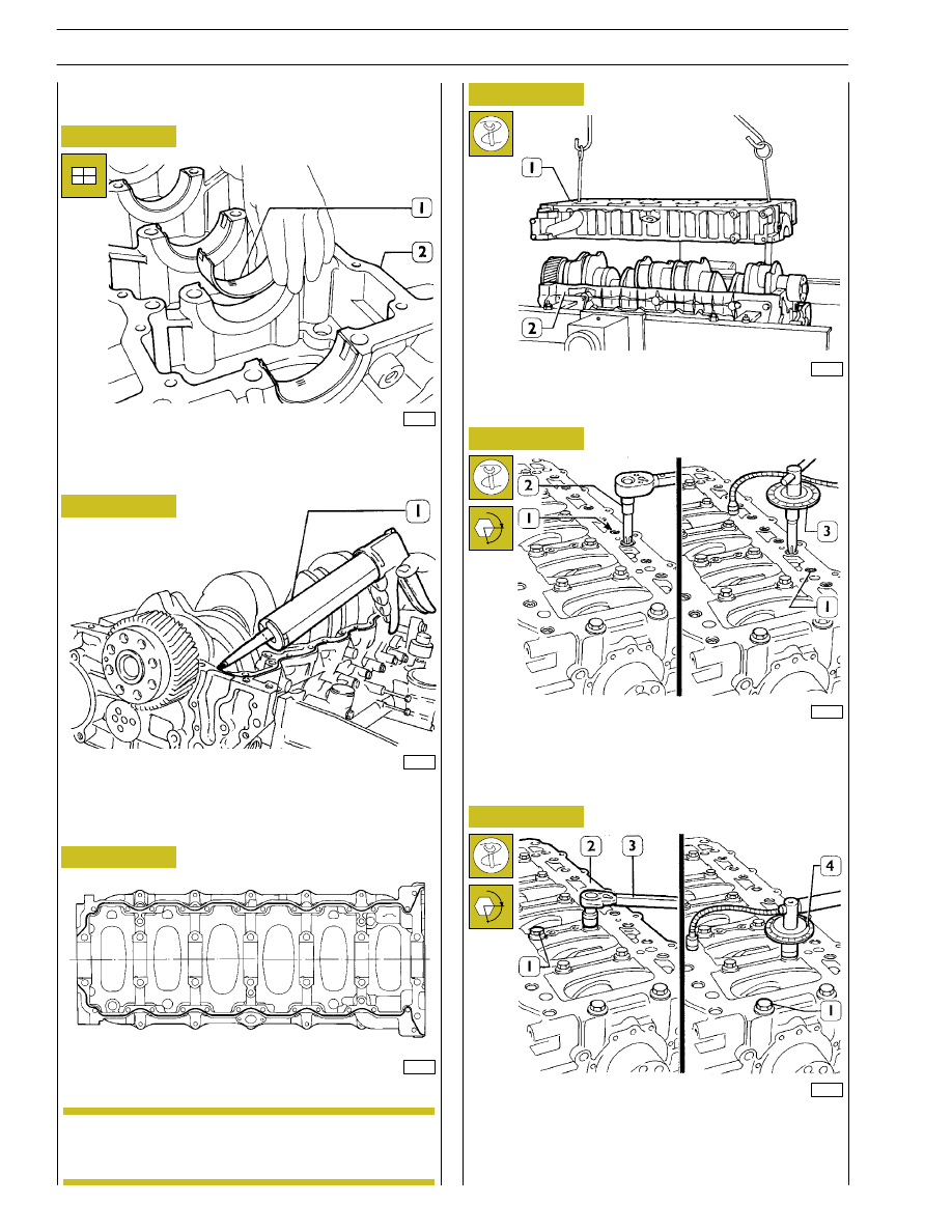
Place the half-bearings (1) on the main bearings in the
underblock (2).
By means of suitable equipment (1) apply silicone LOCTITE
5970 IVECO No. 2992644 to the block, as shown in the
figure.
Sealant application diagram
Fit the underblock within 10’ of the application of
the sealant.
Figure 44
49021
47581
Figure 45
Figure 46
Fit the sub-engine block and use a dynamometric wrench (2)
to tighten the outer hexagonal-grooved screws (1) to 30 Nm
according to the diagrams on the following page.
Fit the underblock by means of a suitable hoist and hooks (1).
49022
47579
Figure 47
Close the inner screws (1) to 120 Nm torque by means of
a dynamometric wrench (3), then with two further angular
phases 60
° + 55°, using tool 99395216 (4). Tighten again the
outer screws (1, Figure 46) with 60
° angular closing, using
tool 99395216 (3, Figure 46).
α
α
ASSEMBLING
THE
ENGINE
ON
THE
BENCH
NOTE
28
SECTION 4 - OVERHAUL AND TECHNICAL SPECIFICATIONS
Нет комментариевНе стесняйтесь поделиться с нами вашим ценным мнением.
Текст