Engine Iveco C10/C13/C78/Cursor 13/Cursor 78. Manual — part 102
47576
47571
47570
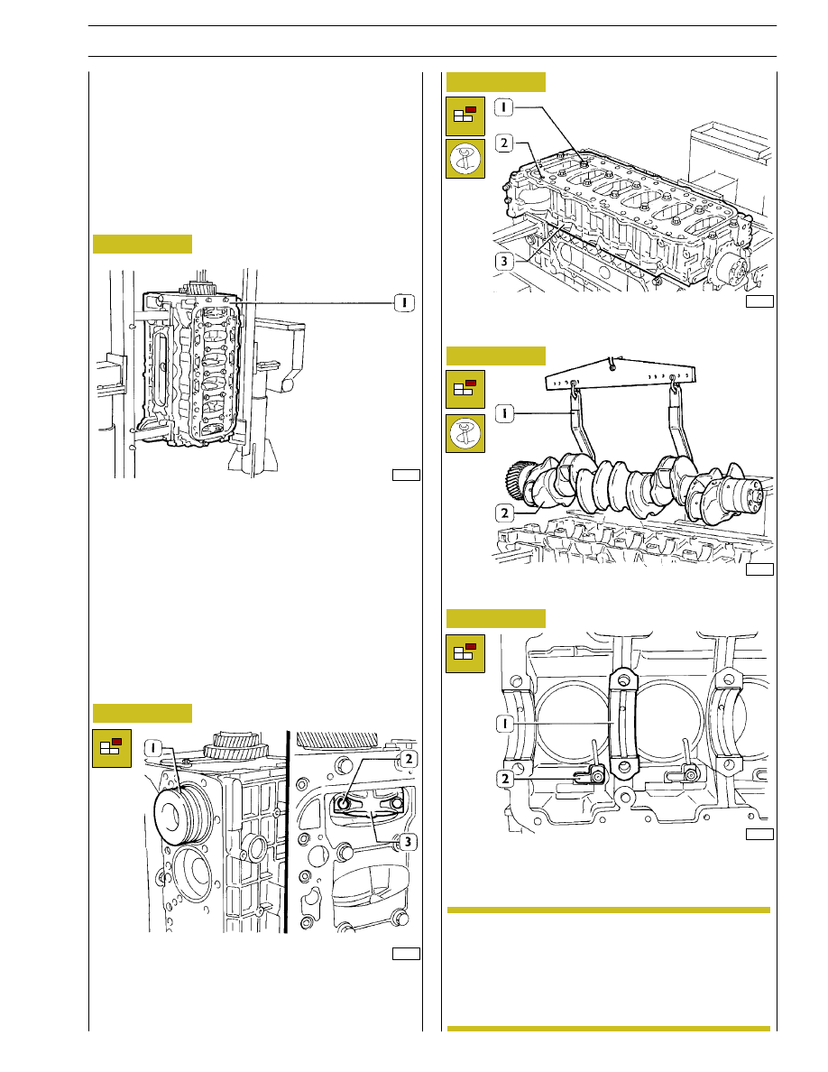
By means of proper and splined wrenches, untighten the
screws (1) and (2) and remove the under-block (3).
Remove the crankshaft (2) with tool 99360500 (1).
Remove the crankshaft half-bearings (1), untighten the
screws and remove oil spray nozzles (2).
Take down cylinder liners as specified in the relative
paragraph on page 16.
After disassembling the engine, thoroughly clean
disassembled parts and check their integrity.
Instructions for main checks and measures are
given in the following pages, in order to determine
whether the parts can be re-used.
Untighten screws (2) fixing the connecting rod cap (3) and
remove it. Remove the connecting rod-piston assembly from
the upper side. Repeat these operations for the other pistons.
Figure 1
Figure 2
Figure 3
Figure 4
Figure 5
Rotate the block (1) to the vertical position.
47575
47574
ENGINE OVERHAUL
ENGINE REMOVAL AT THE BENCH
The
following
instructions
are
prescribed
on
the
understanding that the engine has previously been placed on
the rotating bench and that removal of all specific
components of the equipment have been already removed
as well. (See Section 3 of the manual herein).
The section illustrates therefore all the most important
engine overhaul procedures.
NOTE
SECTION 4 - OVERHAUL AND TECHNICAL SPECIFICATIONS
13
A = Selection class Ø 135.000 to 135.013 mm
B = Selection class Ø 135.011 to 135.024 mm
X = Selection class marking area
On finding maximum wear greater than 0.150 mm or
maximum ovalization of 0.100 mm compared to the values
shown in the figure, you need to replace the cylinder liner as
no grinding, facing or reconditioning is permitted.
REPAIR OPERATIONS
CYLINDER BLOCK
Checks and measurements
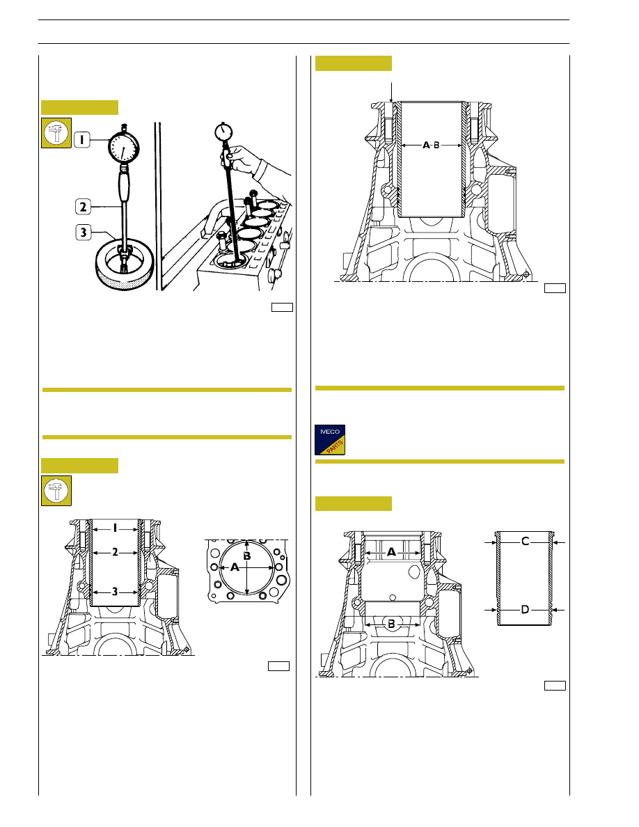
Internal diameter of the cylinder liners is checked for
ovalization, taper and wear, using a bore dial (1) centesimal
gauge 99395687 (2) previously reset to ring gauge (3),
diameter 135 mm.
If a 135 mm ring gauge is not available use a
micrometer caliper.
A = Ø 153.500 to 153.525 mm
B = Ø 152.000 to 152.025 mm
C = Ø 153.461 to 153.486 mm
D = Ø 151.890 to 151.915 mm
The diagram shown in the figure gives the outside diameter
of the cylinder liner and inside diameter of its seat.
The cylinder liners can, if necessary, be extracted and fitted
several times in different seats.
34994
60595
60597
Figure 6
Figure 7
Figure 8
Figure 9
1 = 1
st
measurement
2 = 2
nd
measurement
3 = 3
rd
measurement
The measurements have to be made on each single cylinder
liner at three different heights and on two levels (A-B) at right
angles to each other as shown in Figure 7.
(Demonstration)
The cylinder liners are supplied as spare parts with
selection class ”A”.
60596
x
NOTE
NOTE
14
SECTION 4 - OVERHAUL AND TECHNICAL SPECIFICATIONS

101503
Figure 10
Figure 11
MAIN CYLINDER LINER DATA
DETAIL “X”
“Y“ - Selection class marking area
Figure 12
CRANKCASE ASSEMBLY WITH CYLINDER LINERS
A 125.000 to 125.013 mm
B 125.011 to 125.024 mm
Selection class
60598
101502
Cylinder liners
SECTION 4 - OVERHAUL AND TECHNICAL SPECIFICATIONS
15
47577
16798
60521
Figure 13
Figure 14
Figure 15
Figure 16
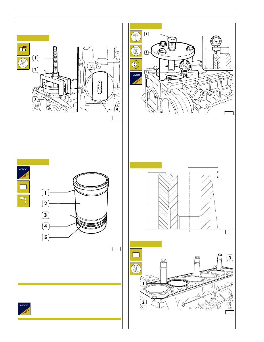
Position the parts 99360706 (2) and the plate 99360728 (4)
as shown in the figure, checking that the plate (4) rests on the
cylinder liner correctly.
Screw down the nut of screw (1) and extract the cylinder
liner (3) from the crankcase.
Always replace the water seals (3, 4 and 5).
Fit the adjustment ring (1) on the cylinder liner (2). Lubricate
the bottom of it and mount it in the cylinder assembly using
the appropriate tool.
Check the protrusion of the cylinder liners with tool 99360334
(2) and tightening the screw (1) to a torque of 225 Nm.
Using the dial gauge 99395603 supplied as standard with the
dial gauge base 99370415 (3), check that the protrusion of
the cylinder liner over the supporting face of the cylinder
head is 0.045 - 0.075 mm (Figure 16); if this is not so, replace
the adjustment ring (1) (Figure 14), supplied as a spare part
with several thicknesses.
On completing assembly, lock the cylinder liners (1) to the
crankcase (2) with the pins 99360703 (3).
Assembly and checking protrusion
Figure 17
CYLINDER LINER PROTRUSION
49017
The adjustment ring (1) is supplied as a spare part
with the following thicknesses: 0.08 mm - 0.10 mm
- 0.12 mm - 0.14 mm.
60520
0.045 to 0.075
Replacing cylinder liners
Removal
NOTE
16
SECTION 4 - OVERHAUL AND TECHNICAL SPECIFICATIONS
Нет комментариевНе стесняйтесь поделиться с нами вашим ценным мнением.
Текст