Engine Iveco C10/C13/C78/Cursor 13/Cursor 78. Manual — part 43
2
SECTION 2 - FUEL

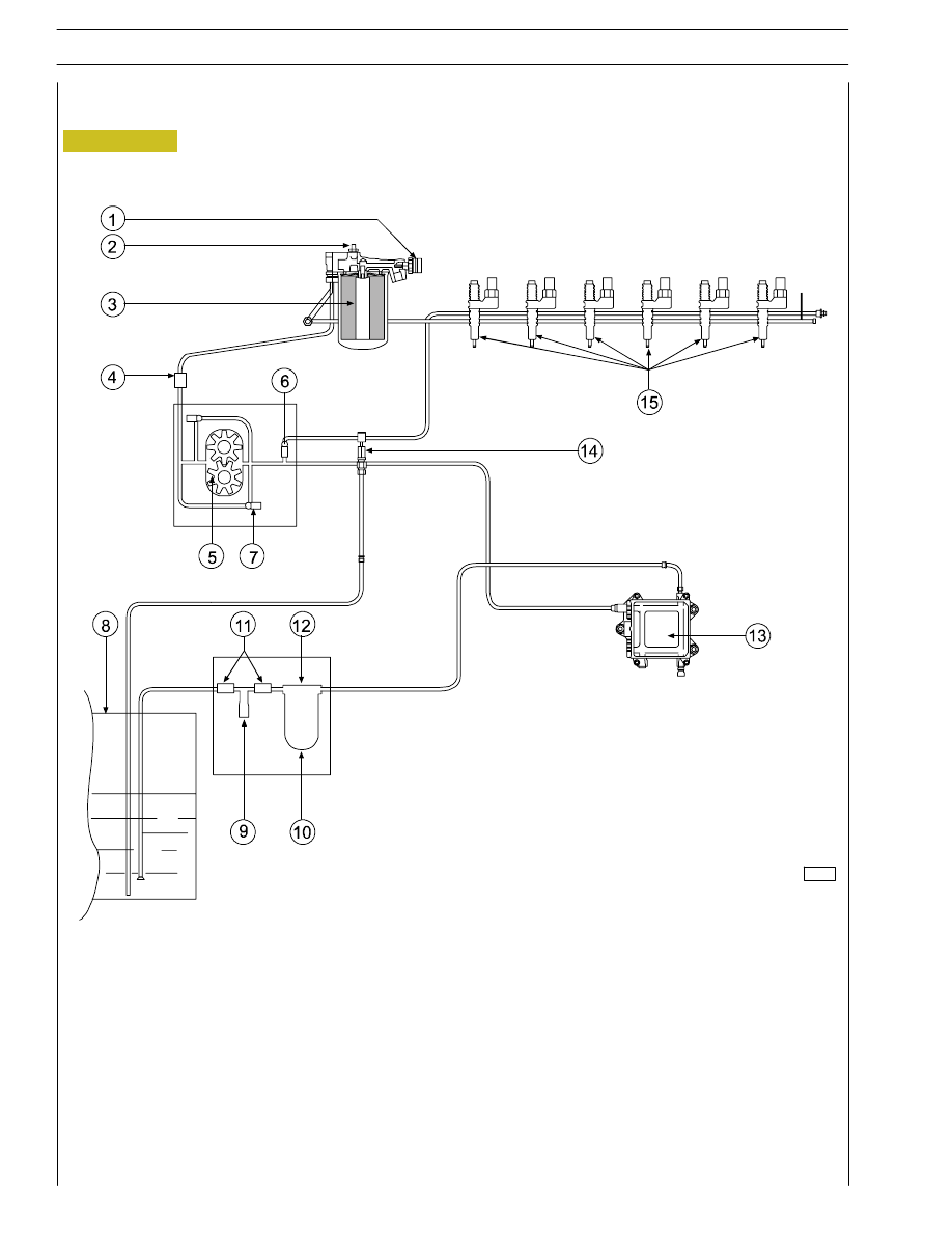
Figure 1
92828
FUEL FEED
Fuel feed is obtained by means of a pump, fuel filter and
pre-filter, 6 pump-injectors controlled by the camshaft by
means of rockers and by the electronic control unit.
Return circuit
Delivery circuit
ENGINE FUEL SUPPLY DIAGRAM WITH FUEL PUMP ON THE TIMING SYSTEM CONTROL
1. Fuel filter - 2. Valve for fuel recirculation from injectors integrated in the fuel pump (start opening 3,5 bar) - 3. Fuel pump
- 4. Overpressure valve for fuel return to the tank (start opening 0,2 bar) - 5. Pressure control valve (start opening 5 bar) -
6. Prefilter with priming pump - 7. Connector - 8. Gearcase - 9. Heat exchanger - 10. Pump injectors.
A. Fuel arrival from injectors - B. Fuel return to the tank - C. Fuel inlet from injectors in the fuel filter
SECTION 2 - FUEL
3
81817
Figure 2
1. Temperature sensor - 2. Bleed valve - 3. Secondary fuel filter - 4. By-pass valve (0.3
÷ 0.4 bar) - 5. Fuel supply pump -
6. Integrated valve (3.5 bar) - 7. Pressure relief valve (5 bar) - 8. Fuel tank - 9. Priming pump - 10. Primary fuel filter -
11. Check valve (opening 0.1 bar) - 12. Heater - 13. Electronic control unit - 14. Fuel return union with valve built in
(0.2 bar) - 15. Pump-injectors.
FUEL SUPPLY DIAGRAM (ALL TYPES)
4
SECTION 2 - FUEL
73547
44908
98870
Figure 3
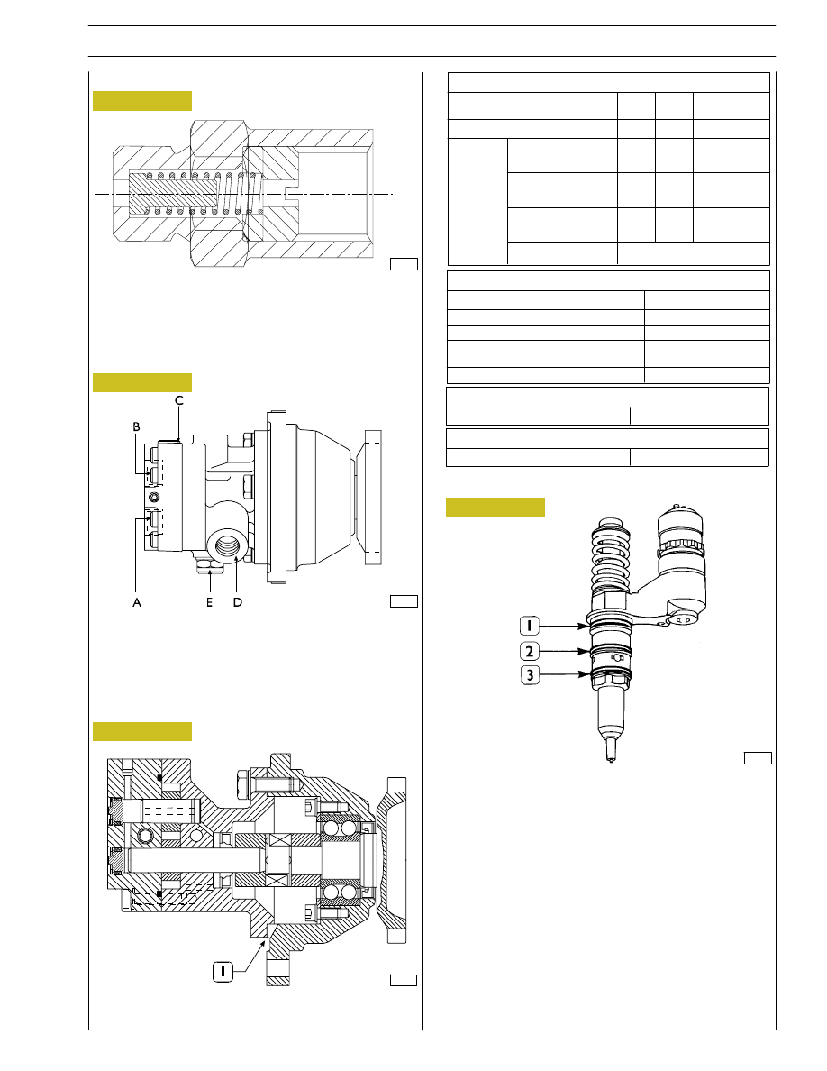
Fuel pump mounted on timing system
A. Fuel inlet — B. Fuel delivery — C. By-pass nut —
D. Fuel return from the pump-injectors —
E. Pressure relief valve — Opening pressure: 5-8 bars.
CROSS-SECTION OF THE FUEL PUMP
1. Oil and fuel leakage indicator.
1. Fuel/oil seal — 2. Fuel/diesel seal — 3. Fuel/exhaust gas seal.
The injector-pump is composed of: pumping element, nozzle,
solenoid valve.
Fuel pump
Figure 4
Figure 5
Injector-pump
Figure 6
92829
An overpressure valve is a single-acting valve, calibrated to 0.2
÷ 0.3 bar, placed on the piping that returns fuel to tank. The
overpressure valve prevents fuel duct in cylinder head from
emptying with engine stopped.
Overpressure valve
Pump performances
Pump rotation speed
(rpm)
Minimum flow rate
(l/h)
4100
310
900
45
250
12
140
6
Test
conditions
Negative pressure
on aspiration
(bar)
Pressure on delivery
(bar)
Test liquid
temperature
(˚C)
Test liquid
0.5
5
30
0.3
3
30
0.3
0,3
30
0.3
0.3
20
ISO 4113
Field of use
Pump rotation speed
(rpm)
Overrunning rotation speed (max 5 min) (rpm)
Diesel oil temperature
(˚C)
Filtering rate on aspiration
(micron)
Negative pressure on aspiration (bar)
2600
4100 max
-25/+80
30
0.5 max
Pressure control valve
Valve calibration
5
÷ 5.8
Injectors return valve
Valve calibration
3.2
÷ 3.8
Pumping element
The pumping element is operated by a rocker arm governed
directly by the cam of the camshaft.
The pumping element is able to ensure a high delivery
pressure. The return stroke is made by means of a return
spring.
Nozzle
Garages are authorized to perform fault diagnosis solely on
the entire injection system and may not work inside the
injector-pump, which must only be replaced.
SECTION 2 - FUEL
5
Нет комментариевНе стесняйтесь поделиться с нами вашим ценным мнением.
Текст