Engine Iveco C10/C13/C78/Cursor 13/Cursor 78. Manual — part 61

2
SECTION 4 - OVERHAUL AND TECHNICAL SPECIFICATIONS
Page
- Fitting connecting rod - piston assemblies
in the cylinder liners
36
. . . . . . . . . . . . . . . . . . . . .
- Checking piston protrusion
36
. . . . . . . . . . . . . . .
- Checking crankpin assembly clearance
37
. . . . . . .
CYLINDER HEAD
37
. . . . . . . . . . . . . . . . . . . . . . . .
- Dismounting the valves
37
. . . . . . . . . . . . . . . . . .
- Checking head bearing surface on cylinder block
37
- Valves
38
. . . . . . . . . . . . . . . . . . . . . . . . . . . . . . . .
- Decarbonizing and checking valves
38
. . . . . . . . .
- Valve seats
38
. . . . . . . . . . . . . . . . . . . . . . . . . . . .
- Checking clearance between valve-stem and
associated valve guide
39
. . . . . . . . . . . . . . . . . . .
- Valve guides
39
. . . . . . . . . . . . . . . . . . . . . . . . . . .
- Replacing injector cases
39
. . . . . . . . . . . . . . . . . .
- Checking injector protrusion
41
. . . . . . . . . . . . . .
TIMING GEAR
42
. . . . . . . . . . . . . . . . . . . . . . . . . .
- Camshaft drive
42
. . . . . . . . . . . . . . . . . . . . . . . . .
Page
- Idler gear pin
42
. . . . . . . . . . . . . . . . . . . . . . . . . .
- Idler gear
42
. . . . . . . . . . . . . . . . . . . . . . . . . . . . .
- Twin intermediate gear pin
42
. . . . . . . . . . . . . . .
- Twin idler gear
42
. . . . . . . . . . . . . . . . . . . . . . . . .
- Replacing the bushings
42
. . . . . . . . . . . . . . . . . . .
- Camshaft
43
. . . . . . . . . . . . . . . . . . . . . . . . . . . . .
- Checking cam lift and pin alignment
43
. . . . . . . . .
- Camshaft
44
. . . . . . . . . . . . . . . . . . . . . . . . . . . . .
- Bushings
44
. . . . . . . . . . . . . . . . . . . . . . . . . . . . . .
- Valve springs
46
. . . . . . . . . . . . . . . . . . . . . . . . . .
- Fitting valves and oil seal
47
. . . . . . . . . . . . . . . . .
ROCKER SHAFT
47
. . . . . . . . . . . . . . . . . . . . . . . . .
- Shaft
48
. . . . . . . . . . . . . . . . . . . . . . . . . . . . . . . . .
- Rocker arms
48
. . . . . . . . . . . . . . . . . . . . . . . . . . .
REAR POWER TAKEOFF
49
. . . . . . . . . . . . . . . . . .
- Removal
49
. . . . . . . . . . . . . . . . . . . . . . . . . . . . . .
- Refitting
49
. . . . . . . . . . . . . . . . . . . . . . . . . . . . . .
TIGHTENING TORQUE
50
. . . . . . . . . . . . . . . . . .
SECTION 4 - OVERHAUL AND TECHNICAL SPECIFICATIONS
3
GENERAL CHARACTERISTICS
Type
F3A
Cycle
4-stroke Diesel engine
Fuel feed
Turbocharged
Injection
Direct
No. of cylinders
6 in line
∅
Bore
mm
125
Stroke
mm
140
+
+
+.. =
Total displacement
cm
3
10300
4
SECTION 4 - OVERHAUL AND TECHNICAL SPECIFICATIONS
Type
F3A
Type
F3AE0684
F3AE0687
A
B
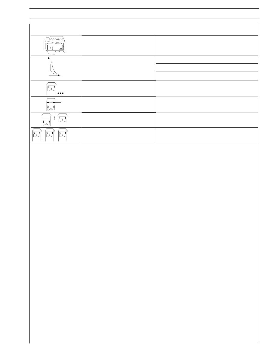
VALVE TIMING
opens before T.D.C.
A
closes after B.D.C.
B
16
°
32
°
16
°
32
°
C
D
opens before B.D.C.
D
closes after T.D.C.
C
51
°
11
°
50
°
9
°
X
For timing check
mm
X
mm
Running
mm
X
mm
-
-
0.40 to 0.50
0.40 to 0.50
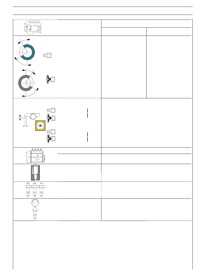
FEED
Through fuel pump - filters
Injection
type: Bosch
With electronically regulated injectors PDE 31
pump injectors controlled by overhead camshaft
Nozzle type
Nozzle type
_
Injection order
1 - 4 - 2 - 6 - 3 - 5
bar
Injection pressure
bar
Injector calibration
bar
1500
296
± 6

SECTION 4 - OVERHAUL AND TECHNICAL SPECIFICATIONS
5
ASSEMBLY CLEARANCE DATA
Type
F3A
CYLINDER BLOCK AND
CRANKMECHANISM COMPONENTS
mm
∅1
Bores for cylinder liners:
upper
∅1
lower
142.000 to 142.025
140.000 to 140.025
Cylinder liners:
L
external diameter:
upper
∅2
lower
141.961 to 141.986
139.890 to 139.915
∅2
length
L
-
Cylinder liners -
crankcase bores
upper
lower
0.014 to 0.064
0.085 to 0.135
External diameter
∅2
-
Cylinder sleeve
∅3
inside diameter
∅3A*
125.000 to 125.013
X
inside diameter
∅3B*
125.011 to 125.024
Protrusion
X
0.045 to 0.075
* Selection class
∅
Pistons:
NUERAL
MAHLE - MONDIAL
∅1
X
measuring dimension
X
18
18
X
external diameter
∅1A
F
124.884 to 124.896
124.881 to 124.893
∅2
external diameter
∅1B
FF
124.895 to 124.907
124.892 to 124.904
∅2
pin bore
∅2
50.010 to 50.016
50.010 to 50.018
Piston - cylinder sleeve
A*
B*
0.107 to 0.132
0.096 to 0.131
* Selection class
Piston diameter
∅1
-
X
Pistons protrusion
X
0.23 to 0.53
3
∅
Gudgeon pin
∅3
49.994 to 50.000
Gudgeon pin - pin housing
0.010 to 0.024
0.010 to 0.024
F
Class A pistons supplied as spares.
FF
Class B pistons are fitted in production only and are not supplied as spares.
Нет комментариевНе стесняйтесь поделиться с нами вашим ценным мнением.
Текст