Engine Iveco C10/C13/C78/Cursor 13/Cursor 78. Manual — part 123
SECTION 2 - APPLICATION G-DRIVE
9
Type
F2B
Type
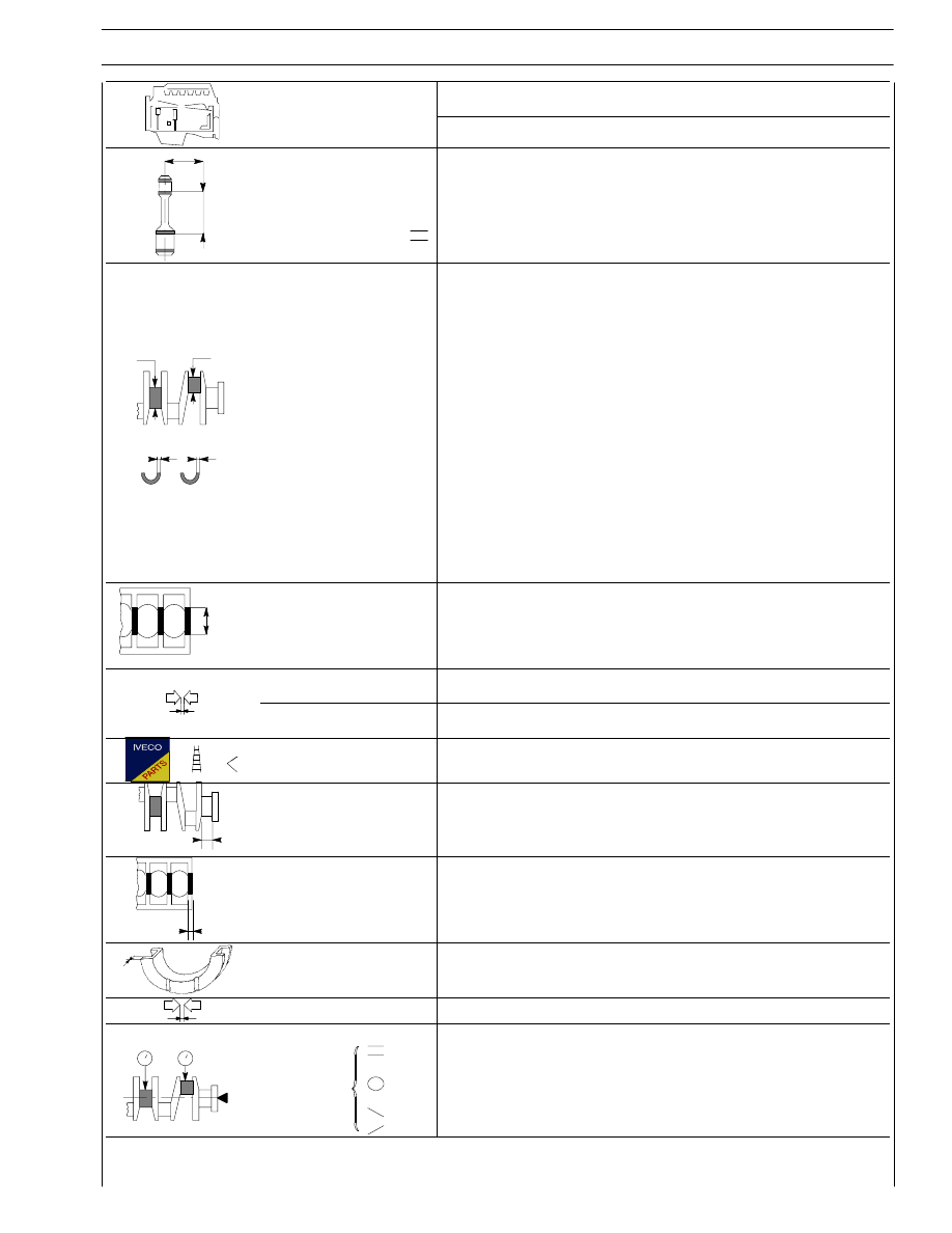
mm
X
Measuring dimension
X
125
Max. connecting rod
axis misalignment
tolerance
0.08
1
2
∅
∅
1
2
Main journals
∅1
- nominal
- class
1
- class
2
- class
3
Crankpins
∅2
- nominal
- class
1
- class
2
- class
3
82.910 to 82.940
82.910 to 82.919
82.920 to 82.929
82.930 to 82.940
72.915 to 72.945
72.915 to 72.924
72.925 to 72.934
72.935 to 72.945
S 1
S 2
Main bearing shells
S1
Red
Green
YellowD
3.000 to 3.010
3.011 to 3.020
3.021 to 3.030
Big end bearing shells
S2
Red
Green
YellowD
2.000 to 2.010
2.011 to 2.020
2.021 to 2.030
3
∅
Main bearing housings
∅3
- nominal
- class
1
- class
2
- class
3
89.000 to 89.030
89.000 to 89.009
89.010 to 89.019
89.020 to 89.030
Bearing shells -
main journals
0.040 to 0.098 * - 0.040 to 0.0110 **
Bearing shells -
big ends
0.035 to 0.093 * - 0.035 to 0.083 **
Main bearing shells
0.127 - 0.254 - 0.508
Big end bearing shells
0.127 - 0.254 - 0.508
X1
Main journal,
thrust bearing
X1
39.96 to 40.04
X2
Main bearing housing,
thrust bearing
X2
32.94 to 32.99
X 3
Thrust washer
halves
X3
3.38 to 3.43
Driving shaft shoulder
0.11 to 0.34
1
2
Alignment
1 - 2
Ovality
1 - 2
Taper
1 - 2
≤ 0.05
_0.010
0.010
D
Fitted in production only and not supplied as spares
f
Spares provided: : * = standard spares - 0.127; ** = 0.254 - 0.508

10
SECTION 2 - APPLICATION G-DRIVE
Type
F2B
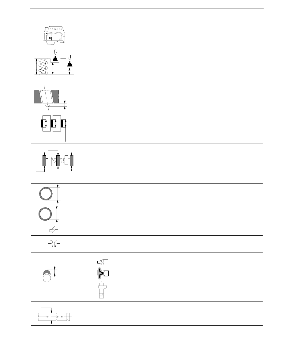
CYLINDER HEADS - VALVE TRAIN
mm
∅
1
Valve guide housings
in cylinder head
∅1
12.980 to 12.997
2
∅
∅ 2
8.023 to 8.038
∅
3
∅ 2
Valve guide
∅ 3
13.012 to 13.025
Valve guides - housings
in the cylinder heads
0.015 to 0.045
Valve guide
0.2 to 0.4
∅
4
Valves:
∅
Valves:
∅ 4
7.970 to 7.985
∅ 4
α
60
° 30′ ± 7′ 30″
∅ 4
7.970 to 7.985
α
∅ 4
α
45
° + 15′
Valve stem and its guide
0.038 to 0.068
Housing in head for valve
seat
seat
∅1
41.985 to 42.020
∅
1
∅1
40.985 to 41.020
Outside diameter of valve
2
∅
Outside diameter of valve
seat; angle of valve seat in
cylinder head:
∅ 2
42.060 to 42.075
α
60
° - 30’
α
∅ 2
41.060 to 41.075
∅ 2
α
45
° - 30′
Recessing of
valve
0.5 to 0.8
X
valve
X
1.6 to 1.9
Between valve
Between valve
seat and head
0.040 to 0.090
SECTION 2 - APPLICATION G-DRIVE
11
Type
F2B
mm
Valve outside spring
height:
free height
H
63.6
H
H 1
2
under a load of:
H 1
H 2 N 454 ± 22
H1
49.5
N 840
± 42
H2
37.5
X
Injector protrusion
X
0.7
∅
∅
∅
Camshaft
bush
housing
fitted in the cylinder head:
1
⇒ 7
Ø
80.000 to 80.030
∅
∅
∅
1
2
3
Camshaft journal diameter:
1
⇒ 7
Ø
75.924 to 75.940
∅
Camshaft bushing outer
diameter:
∅
80.090 to 80.115
∅
Camshaft bushing
inner diameter:
∅ 6
∅ 7
75.990 to 76.045
76.008 to 76.063
Bushings and housings in
engine block
0.060 to 0.115
Bushings and
journals
1
⇒ 6
7
0.050 to 0.121
0.068 to 0.139
Cam lift:
8.07
H
7.33
8.820
∅
1
Rocker shaft
∅ 1
37.984 to 38.000
12
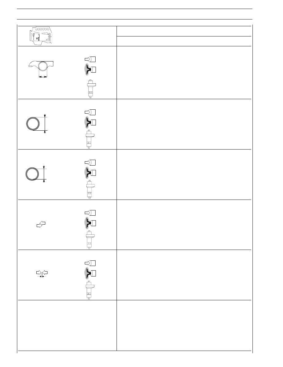
SECTION 2 - APPLICATION G-DRIVE
Type
F2B
mm
Bushing housing in rocker
arms
41.000 to 41.016
41.000 to 41.016
∅
42.000 to 42.016
Bushing outer diameter
for rocker arms:
41.097 to 41.135
∅
41.097 to 41.135
42.066 to 42.091
Bushing inner diameter
for rocker arms:
38.025 to 38.041
∅
38.025 to 38.041
38.015 to 38.071
Between
bushings
and
housings
0.081 to 0.135
0.081 to 0.135
0.050 to 0.091
Between rocker arms and
shaft
0.025 to 0.057
0.225 to 0.057
0.015 to 0.087
TURBOCHARGER
Type
HOLSET HX40W
End float
0.025 to 0.127
Radial play
0.254 to 0.356
Wastegate opening stroke at
1.8
± 0.01 bar pressure:
-
control
-
adjustment
0.33 to 1.27
0.5 to 1.04
Нет комментариевНе стесняйтесь поделиться с нами вашим ценным мнением.
Текст