Engine Iveco C10/C13/C78/Cursor 13/Cursor 78. Manual — part 82
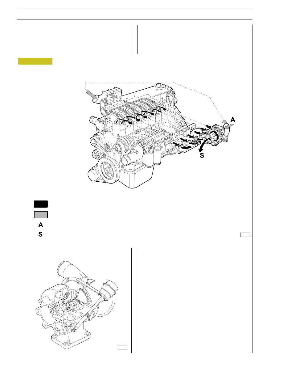
Figure 18
TURBOCHARGING
The turbocharging system consists of:
- air filter;
- Wastegate turbocharger.
101604
Engine exhaust gas
Intake air
A = Inlet
S = Exhaust
HOLSET HX 60W turbocompressor
The turbocompressor is a turbocompressor with a return
valve.
It is mainly composed by:
- a central unit where a shaft is positioned supported by
bushings, a turbine rotor and a compressor rotor are
mounted on each end;
- a turbine unit and a compressor unit mounted at the end
of the central unit;
- return valve applied on the turbine unit. It divides burnt
gases outlet, sending one part directly to the outlet tube
when the boost of the compressor reaches the setting
value.
71766
14
SECTION 1 - GENERAL SPECIFICATIONS
SECTION 2 - FUEL
1
SECTION 2
Fuel
Page
FEEDING
3
. . . . . . . . . . . . . . . . . . . . . . . . . . . . . . .
FUEL SUPPLY DIAGRAM
4
. . . . . . . . . . . . . . . . . .
- Overpressure valve
5
. . . . . . . . . . . . . . . . . . . . .
- Fuel pump
5
. . . . . . . . . . . . . . . . . . . . . . . . . . . .
- Injector-pump
5
. . . . . . . . . . . . . . . . . . . . . . . . .
- Injector Phases
6
. . . . . . . . . . . . . . . . . . . . . . . . .
2
SECTION 2 - FUEL
A
B
Figure 1
92847
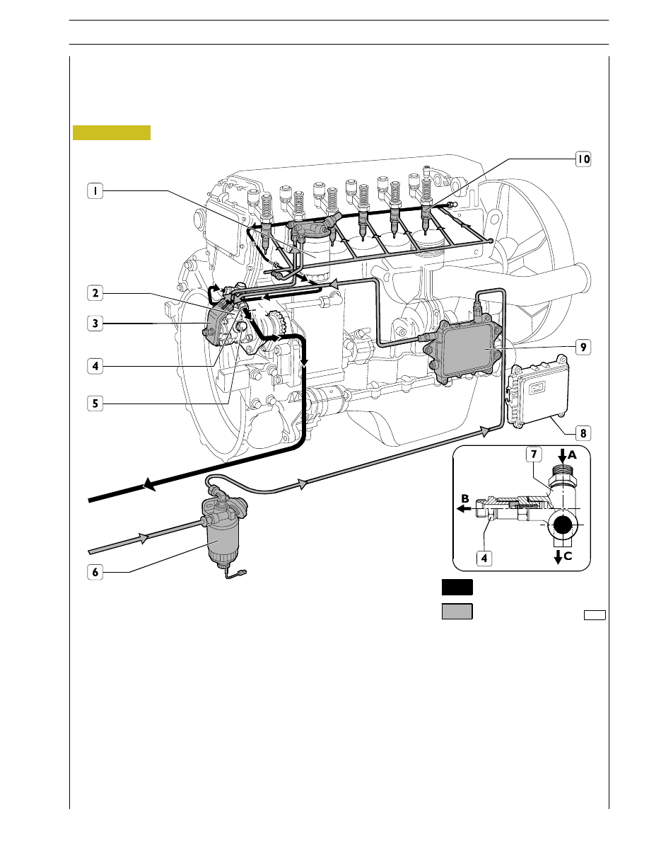
FEEDING
Fuel is supplied via a fuel pump, filter and pre-filter, 6
pump-injectors governed by the camshaft via rocker arms
and by the electronic control unit.
Return circuit
Supply circuit
ENGINE FUEL SUPPLY
1. Fuel filter - 2. Valve for fuel recirculation from injectors integrated in the fuel pump (start opening 3,5 bar) - 3. Fuel pump
- 4. Overpressure valve for fuel return to the tank (start opening 0,2 bar) - 5. Pressure control valve (start opening 5 bar) -
6. Prefilter with priming pump - 7. Connector - 8. Gearcase - 9. Heat exchanger - 10. Pump injectors.
A. Fuel arrival from injectors - B. Fuel return to the tank - C. Fuel inlet from injectors in the fuel filter
SECTION 2 - FUEL
3
Нет комментариевНе стесняйтесь поделиться с нами вашим ценным мнением.
Текст