Loader Bobcat 853, 853H. Manual — part 33
FIXED TENSIONER PULLEY (Cont’d)
Assembly (Cont’d)
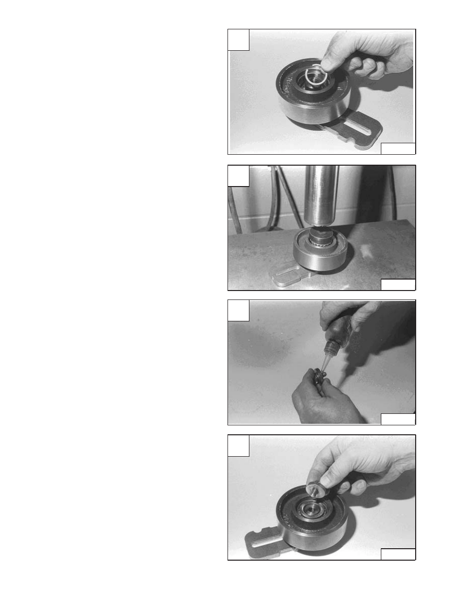
Install the small bearing spacer [A].
Install the taper roller bearing pushing on the I.D. of the
bearing [B].
Put LOCTITE (P/N 6540410) on the bolt threads [C].
Install the bolt and washer into the shaft [D].
A
CD–12648
C
CD–12650
D
CD–12651
–3–38–
853, 853H Loader
Service Manual
B
CD–12649
FIXED TENSIONER PULLEY (Cont’d)
Assembly (Cont’d)
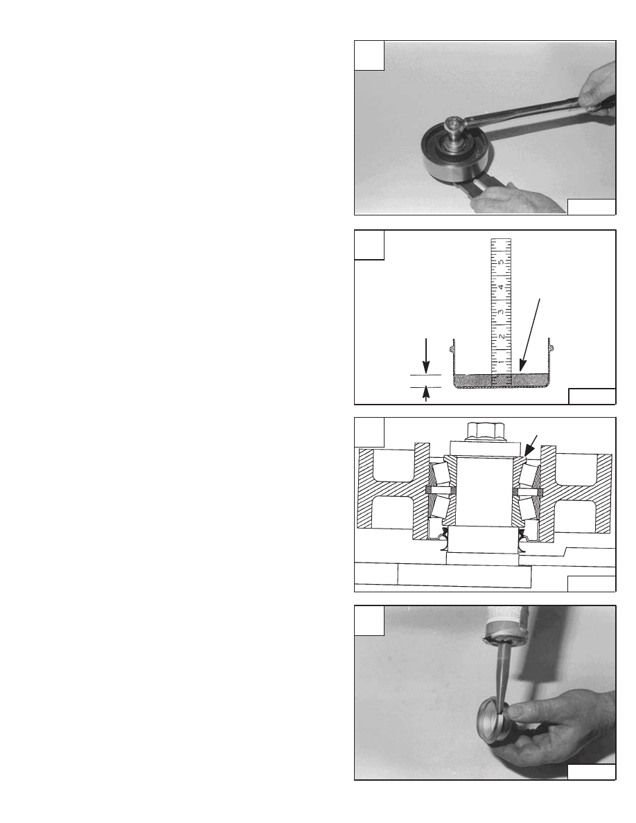
Tighten the bolt to 25–28 ft.–lbs. (43–38 Nm) torque [A].
Use only 15W/50 synthetic oil (Example: Mobil One) for
the bearings. Use the cap and add oil until it is at the 0.50’’
(12,7 mm) mark on the scale, which should be 0.75 oz.
(20 C.C.) of oil [B].
Add the oil slowly, at one location of the bearing which will
allow the trapped air to escape from the other side [C].
Check the cap sealing edge to make sure it is not
damaged. Replace the cap as needed.
Make sure the sealing edge on the hub bore and cap
sealing edge is clean and free of oil, put a bead of sealant
(P/N 6633538) on the cap [D].
Install the cap.
NOTE: Oil capacity is very critical, do not add any
more and/or any less oil to the idler pulley.
A
CD–12652
C
MC–01648
OIL LEVEL
D
CD–12653
853, 853H Loader
–3–39–
Service Manual
B
MC–01648
0.75 oz.
(20 C.C.)
Capacity
0.50’’ (12,7)
Measure Oil
Level in the
Center of the Cap
FIXED TENSIONER PULLEY (Cont’d)
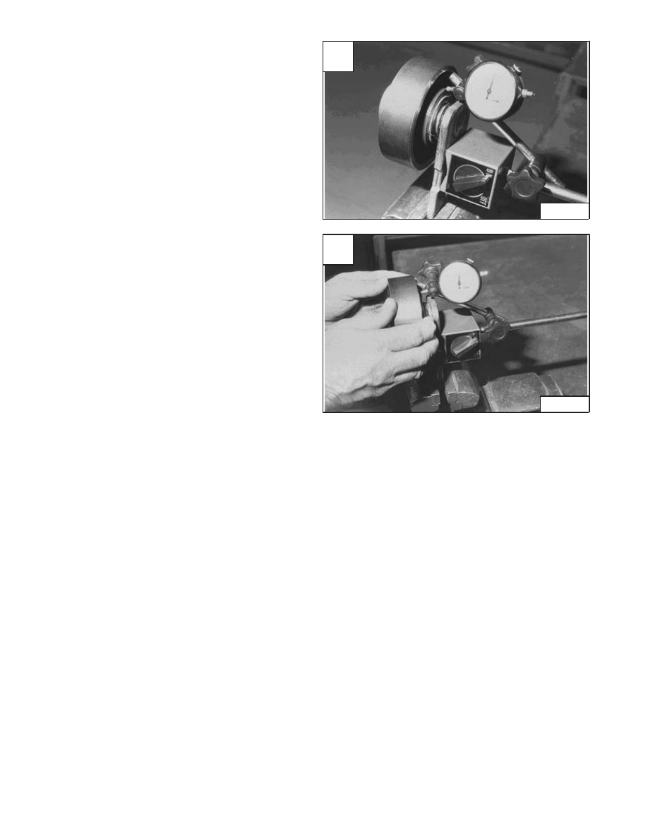
Checking Pulley End Play
Install the pulley/mounting bracket assembly in to vise.
Install a dial indicator on the pulley hub [A].
Move the pulley by hand, back and forth. The correct end
play is 0.005–0.013 inch (0,13–0,33 mm) [B].
If the end play is not correct, there is no adjustment.
Replace the hub, pulley and/or bearings.
A
CD–12655
–3–40–
853, 853H Loader
Service Manual
B
CD–12656
FIXED TENSIONER PULLEY (Cont’d)
Adjusting The Drive Belt
See the SERVICE SCHEDULE Page 1–1 for the service
interval.
To adjust the drive belt between the engine flywheel and
the hydrostatic pump pulley, use the following procedure:
Raise the operator cab. (See Page 1–1.)
Remove the belt shield. (See Page 3–26.)
Use the following tools to check the belt tension:
MEL1404 – Bar
MEL1406 – Spring Scale
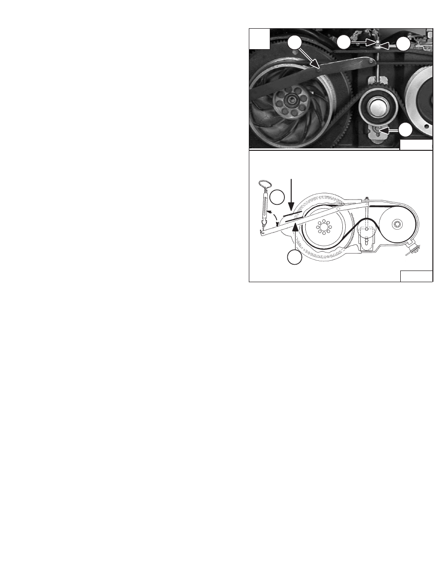
1. Install the tool on the drive belt. The pin (Item 1) [A]
must be pulled tight against the engine drive pulley.
2. Make a mark (Item 2) [A] on the cast flange just
above the tool handle.
3. Install the spring scale on the tool handle. The line
of pull (Item 3) [A] on the spring scale must be at
approximately 90
°
from the tool handle.
4. Loosen bolt (Item 4) [A] and jam nut (Item 5) [A].
5. Tighten adjustment nut (Item 6) [A] to increase belt
tension; loosen to decrease belt tension.
6. Tighten bolt (Item 4) [A] and jam nut (Item 5) [A].
NEW BELT: (less than .5 hours use): With 14 lbs. (62 N)
for force, the tool should move 1.25 inches (32,0 mm) (the
width of the tool handle). Run the engine approximately
5 minutes and readjust the tension.
USED BELT: (more than .5 hours use): With 12 lbs. (52
N) of force, the tool should move 1.25 inches (32,0 mm)
(the width of the tool handle).
Always readjust if a tension check results in a reading of
less than 10 lbs. (44N) of force.
A
B–13459
1
4
6
5
3
2
1.25 ” (32,0 mm)
90
o
P–04927
853, 853H Loader
–3–41–
Service Manual
853, 853H Service Manual #6720755 – Hydrostatic System Section Part 1 of 2
Нет комментариевНе стесняйтесь поделиться с нами вашим ценным мнением.
Текст