Loader Bobcat 773. Manual — part 93
VALVE, VALVE SEAT AND GUIDE (Cont’d)
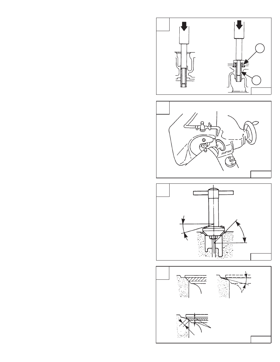
Checking The Valve Guide (Cont’d)
Press the used valve guide out of the cylinder head using
the special driver tool [A].
Put oil on the outside diameter of the new valve guide.
Press the new valve guide into the cylinder head from the
top side. Use the special driver tools (Items 1 & 2) [A],
press the new guide until the tool contacts the cylinder
head.
Ream the valve guide to the correct specifications.
Reconditioning The Valve And Valve Seat
Grind the valve face to the correct angle using a valve
refacer [B].
Grind the valve seat surface in the cylinder head to the
correct angle [C].
Check the seat surface and valve face (Item 1) [D].
If the seat surface is to wide, use a 15 degree cutter (Item
2) [D] to get the correct width (Item 3) [D].
Valve Seat Width
Intake
0.084 inch (2,12 mm)
. . . . . . . . . . . . . . . . . . . . . .
Exhaust
0.084 inch (2,12 mm)
. . . . . . . . . . . . . . . . . . . . .
Valve Seat & Face Angle
Intake
30
°
. . . . . . . . . . . . . . . . . . . . . . . . . . . . . . . . . . . . .
Exhaust
45
°
. . . . . . . . . . . . . . . . . . . . . . . . . . . . . . . . . . . .
A
PI–09992
1
2
C
PI–09994
45
°
(30
°
)
15
°
Intake
Exhaust
D
PI–09995
1
2
3
15
°
773 BICS Loader
–7–51–
Service Manual
B
PI–09993
VALVE, VALVE SEAT AND GUIDE (Cont’d)
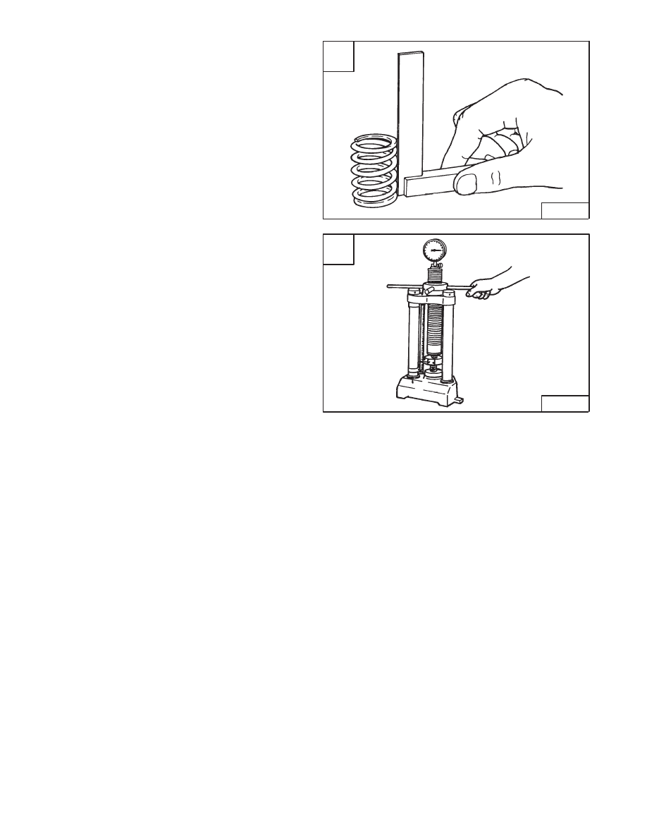
Valve Spring
Measure the length of the valve spring. If the
measurement is less than the allowable limit, replace the
spring [A].
Free Length
1.642–1.661 inch (41,7–42,2 mm)
. . . . . . .
Allowable Limit
1.622 inch (41,2 mm)
. . . . . . . . . . . . . . . .
Put the spring on a flat surface, place a square on the side
of the spring [A].
Rotate the spring and measure the maximum tilt. If the
measurement exceeds the allowable limit, replace the
spring.
Tilt
0.040 inch (1,0 mm)
. . . . . . . . . . . . . . . . . . . . . . . . . . .
Place the spring on a tester and compress to specified
length [B].
Read the compressed load on the gauge. If the
measurement exceeds allowable limit, replace the spring.
Setting Length
1.378 inch (35,0 mm)
. . . . . . . . . . . . . . . .
Setting Load
26.4 lbs. (117,6 N)
. . . . . . . . . . . . . . . . . . . .
Allowable Limit
22.5 lbs. (100,0 N)
. . . . . . . . . . . . . . . . . .
A
B–03680
–7–52–
773 BICS Loader
Service Manual
B
A–02759
D
B–03697
1
2
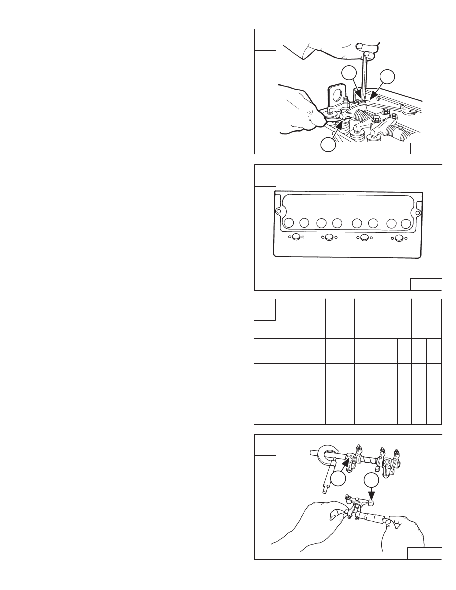
VALVE CLEARANCE
Adjustment
Adjust the valve clearance as follows:
Loosen the lock nut (Item 1) [A].
Turn the adjustment screw (Item 2) [A] until the correct
clearance is obtained.
NOTE: The clearance is measured between the
rocker arm and valve stem tip (Item 3) [A].
Adjust the valve clearance as follows:
0.008 inch (0,20 mm)
Intake & Exhaust
Use the following sequence to set the valves [B] & [C]:
a.
With the rocker arm rocking (valves 7 & 8) on No. 4
cylinder set clearance at No. 1 cylinder (valves 1 & 2).
b.
With the rocker arm rocking (valves 3 & 4) on No. 2
cylinder set clearance at No. 3 cylinder (valves 5 & 6).
c.
With the rocker arm rocking (valves 1 & 2) on No. 1
cylinder set clearance at No. 4 cylinder (valves 7 & 8).
d.
With the rocker arm rocking (valves 5 & 6) on No. 3
cylinder set clearance at No. 2 cylinder (valves 3 & 4).
Revised June 01
ROCKER ARM AND SHAFT
Checking
Measure the rocker arm I.D. (Item 1) [C] with the inside
micrometer.
Measure the rocker arm shaft O.D. (Item 2) [C] with a
outside micrometer.
If the clearance exceeds the allowable limit, replace the
bushing.
If the clearance still exceeds the allowable limit after the
bushing is replaced, replace the rocker arm shaft.
Oil Clearance Between Rocker Arm
& Shaft
0.0006–0.0015 inch (0,016–0,038 mm)
. . . . .
Allowable Limit
0.006 inch (0,15 mm)
. . . . . . . . . . . . . . . .
Rocker Arm Shaft
O.D.
0.550–0.551 inch (13,97–13,98 mm)
. . . . . . . . . .
Rocker Arm I.D. 0.5512–0.5516 inch (14,0–14,01 mm)
A
B–05568
1
3
2
B
B–05569
1
2
3
4
5
6
7
8
C
Cylinder Number
Valve Number
Valve
I = Intake
E = Exhaust
1
2
3
4
1
2
3
4
5
6
7
8
I
E
I
E
I
E
I
E
773 BICS Loader
–7–53–
Service Manual
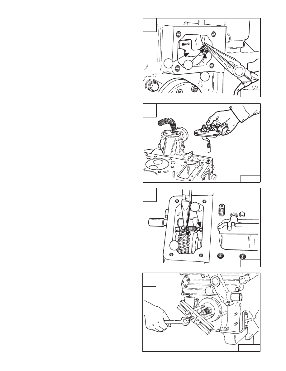
TIMING GEARCASE COVER
Removal And Installation
Remove the fuel injection pump. (See Page 7–40.)
Remove the cylinder head, rocker arms and push rods.
(See Page 7–47.)
Disconnect the two governor springs (Items 1 & 2) [A]
from the fork lever (Item 3) [A].
Remove the speed control plate with the governor springs
[B].
Remove the start spring (Item 1) [C] from the fork lever
(Item 2) [C].
Installation: Be careful; do not drop the spring into the
gearcase.
Remove the crankshaft pulley nut.
Installation: Tighten the nut to 101–116 ft.–lbs.
(137–157 Nm) torque.
Use a puller and remove the crankshaft pulley [D].
A
B–14336
1
2
3
D
B–03694
C
B–14338
2
1
–7–54–
773 BICS Loader
Service Manual
B
B–14337
Нет комментариевНе стесняйтесь поделиться с нами вашим ценным мнением.
Текст