Loader Bobcat 773. Manual — part 113
A
MC–02420
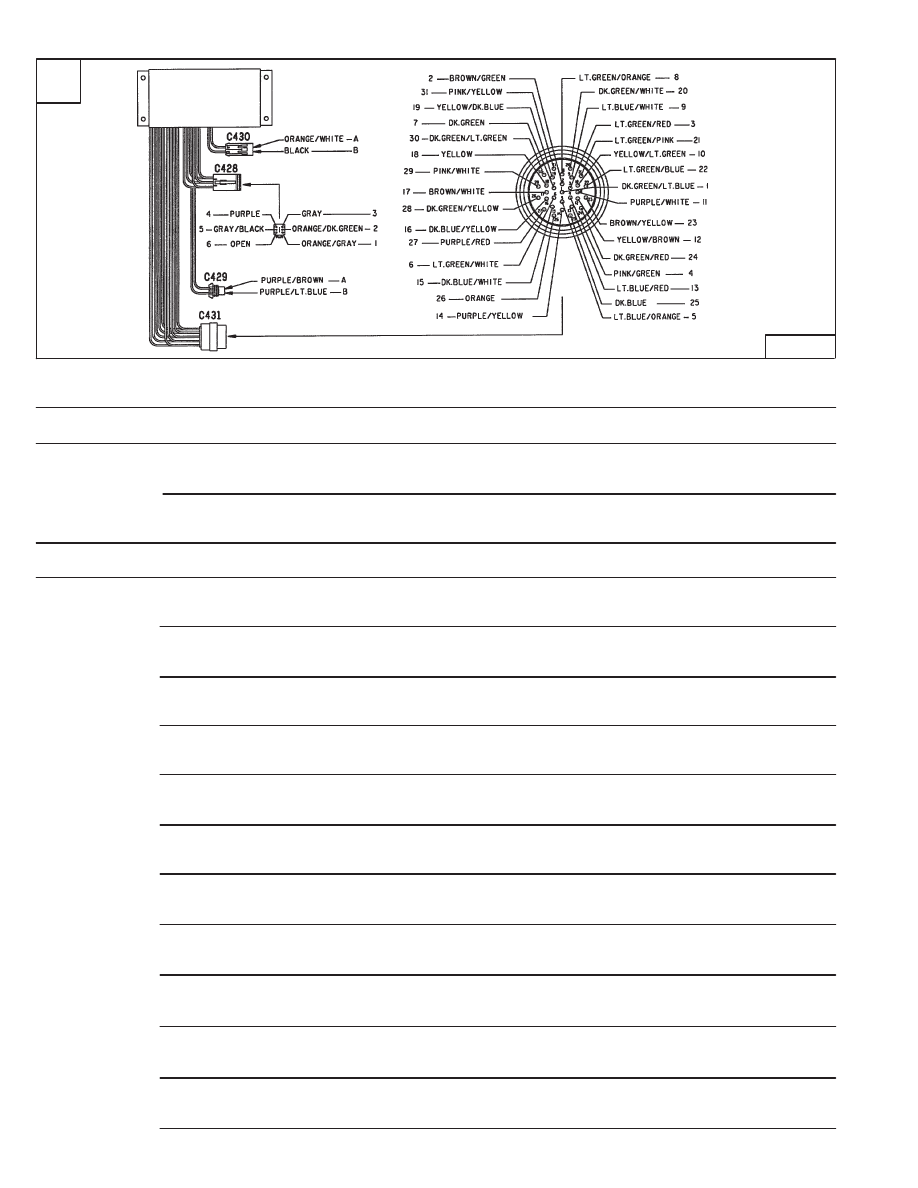
AHC/PWM CONTROLLER (Cont’d)
Description
Connector No. Pin No. Description
Voltage
Comments
C 430*
A
Battery Power
12.0
B
Ground
0
C 428*
1
Power
12.0
2
Model Input
12. 0
3
Model Select–Input A
Not Used
4
Model Select–Input B
Not Used
5
Model Select–Input C
Not Used
6
Open
0
C 429*
A
Diagnostic Light
4.0–11.0
Light ON–Light OFF
B
Diagnostic Light
4.0–11.0
Light ON–Light OFF
C 431*
1
Attachment Control Signal
0 or 12.0
2
Signal from Lift Control Input Handle
0.80–1.89–2.90
Low–Neutral–High
Signal from Lift Control Input Handle (Float)
3.8
3
Return from Aux. Module Switch Input
9.5
4
Signal from Tilt Control Input Handle
0.80–1.89–2.90
Low–Neutral–High
5
Power to Tilt Spool Actuator
Not Used
6
Signal from Lift Actuator Feedback Input
0.40–1.72–3.0
Low–Neutral–High
Signal from Lift Actuator Feedback Input (Float)
3.8
7
Return from Aux. Detent Switch Input
12.0
8
Power to Lift Spool Actuator
Not Used
9
Signal from Tilt Actuator Feedback Input
0.40–1.72–3.0
Low–Neutral–High
10
Return from Aux. Rear Base Switch Input
11.0
11
BICS Status Input
0 or 12.0
Bar UP–Bar DOWN
12
Return from Aux. Rear Rod Switch Input
12.0
13
High Flow Solenoid Output
0 or 12.0
14
Diagnostic Input
No function
15
Low Reference to Resistive Inputs
Ground
16
Signal from Aux. Resistive Inputs
0.98–2.24–3.24
Low–Neutral–High
17
Lift Actuator Reverse Motor Output
0 to 12.0
18
Diverter Solenoid Output
12.0
19
BICS Aux. Lock Input
0 or 11.0
Bar UP–Bar DOWN
20
Auxiliary Relief Input
12.0
Key Left
21
Aux. Switch Module Detent Light
3.5 between 8.5 Light ON–Light OFF
22
Aux. Switch Module Momentary Light
3.5–8.5
Light ON–Light OFF
23
Lift Actuator Forward Motor Output
0 to 12.0
24
Aux. Spool Base End Output
0–6.0
Key Left (12 Volt)
25
High Reference to Resistive Inputs
4.3
±
0.1
26
Power to Aux. Switch Module
9.99–10.68
27
AHC Status Output
0 or 12.0
Bar UP–Bar DOWN
28
Switch Power
12.0
Key On
29
Tilt Actuator Reverse Motor Output
0 to 12.0
30
Aux. Spool Rod End Output
0–6.0
31
Tilt Actuator Forward Motor Output
0 to 12.0
*Schematic Connector Number
*
*
*
*
–10–16–
Service Manual
773 BICS Loader
Revised June 01
AHC/PWM CONTROLLER (Cont’d)
•
When the lights are flashing, the key needs to be
turned OFF and then ON. If the problem still exists they
will continue to flash.
•
Proportional flow cannot be engaged if the lights are
blinking.
•
Continuous flow (detent) can be engaged if alternate
blinking lights are OFF after the key switch is turned
OFF and then ON (during a proportional flow switch
failure).
Troubleshooting Chart
The controller sends a diagnostic code to the Auxiliary
Hydraulic Switch lights when the conditions listed in the
chart below occur.
Conditions
•
Auxiliary Hydraulic Switch lights will not come ON.
Check the following:
PWM fuse
Wires disconnected, shorted, or open.
Auxiliary hydraulic switch failure.
Module failure.
Use the voltage tests in the wire identification
section to determine the cause. (See Page
10–16.)
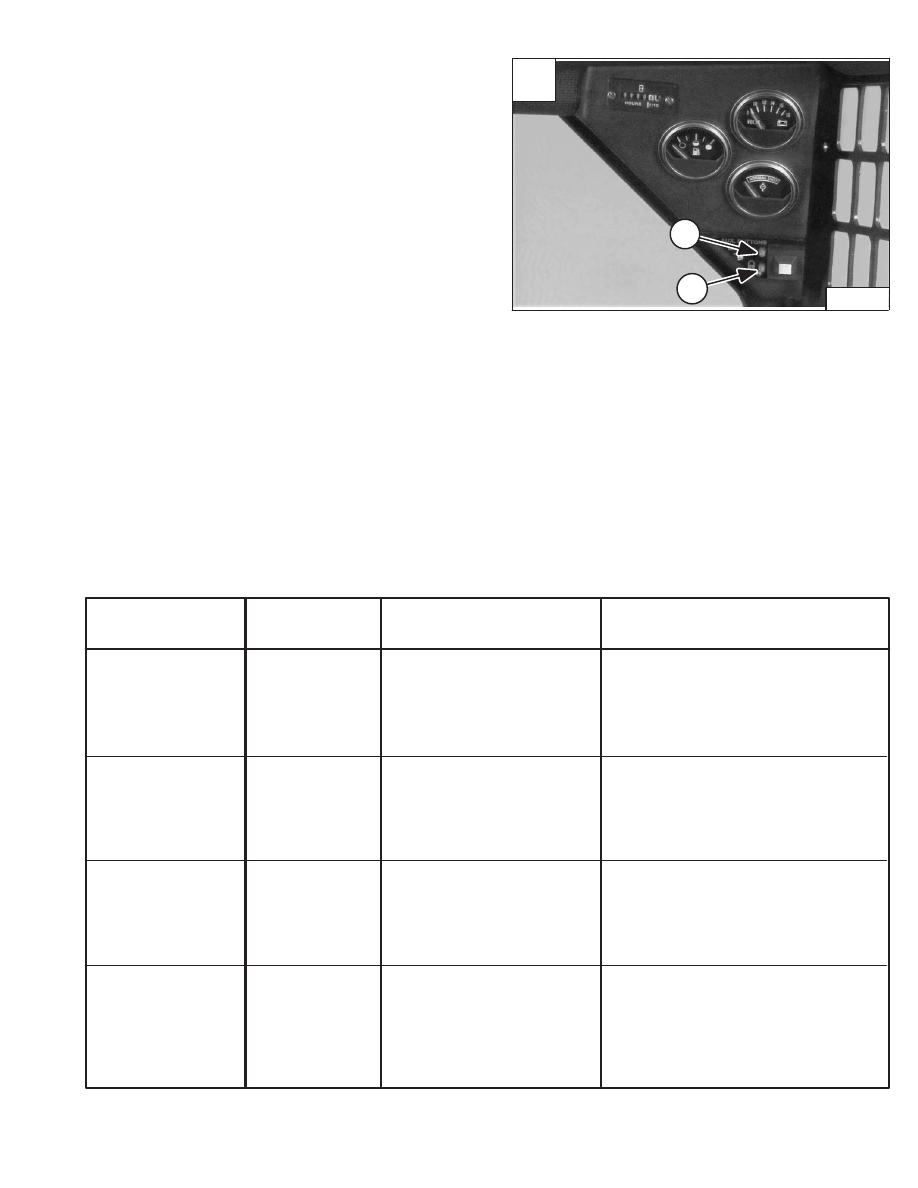
Momentary LED
(Item 1) [A]
Detent LED
(Item 2) [A]
PROBLEM AREA
PROBLEM CAUSE
Light Blinking
Light Off
Light Blinking
*Blinking/OFF
Light OFF
Light Blinking
Light Blinking
*OFF/Blinking
Base End Solenoid or Wiring
Rod End Solenoid or Wiring
Diverter Solenoid or Wiring
Proportional Flow Switch
(Right Handle)
•
Wires Disconnected
•
Wires Shorted
•
Wires Open
•
Solenoid failed. Perform solenoid
coil test.
•
PWM module failed.
•
Wires Disconnected
•
Wires Shorted
•
Wires Open
•
Solenoid failed. Perform solenoid
coil test.
•
PWM module failed.
•
Wires Disconnected
•
Wires Shorted
•
Wires Open
•
Solenoid failed. Perform solenoid
coil test.
•
PWM module failed.
•
Wires Disconnected
•
Wires Shorted
•
Wires Open
•
Proportional flow switch failed.
Check voltage to switch.
Perform handle test.
•
PWM module failed.
*Alternate Blinking Lights
A
P–03272
2
1
–10–17–
Service Manual
773 BICS Loader
Revised Nov. 01
AHC/PWM CONTROLLER (Cont’d)
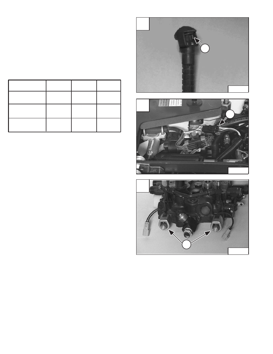
Handle Testing
The right side steering lever handle switch (Item 1) [A]
controls the proportional flow to front auxiliary. Use a Ohm
meter to test the switch.
Disconnect the handle switch harness from the controls
harness (Item 1) [B]. Use the chart below to test the
handle switch.
Handle Switch Position
Test between
handle wires
Dk. Blue &
Dk. Blue/White
Dk. Blue/Yellow
& Dk. Blue/White
Dk. Blue/Yellow
& Dk. Blue
Full Left
4.5–5.5
K–Ohms
0.5–1.5
K–Ohms
3.5–4.5
K–Ohms
Center
4.5–5.5
K–Ohms
2.3–2.7
K–Ohms
2.3–2.7
K–Ohms
Full Right
4.5–5.5
K–Ohms
3.5–4.5
K–Ohms
0.5–1.5
K–Ohms
NOTE: Push the switch gradually from center to
either left or right. The Ohm reading must
change gradually. Replace the handle switch
assembly if required.
Solenoid Coil Testing
The front auxiliary solenoid coils (Item 1) [C] are located
in the hydraulic control valve. Test the solenoid coils with
a Ohm test meter.
Disconnect the coil from the controls harness. The correct
reading is 1–5 Ohms.
One K–Ohm is equal to 1000 Ohms.
1
B
N–17779
A
P–02129
1
–10–18–
Service Manual
773 BICS Loader
Revised June 01
C
N–17493
1

B
N–17783
1
A
N–17774
1
2
CONTROL HANDLE (ADVANCED HAND CONTROL)
(AHC)
Control Handle Unit Removal And Installation
To remove the handle control unit, slide the rubber handle
cover (Item 1) [A] up the handle.
Remove the two mounting bolts (Item 2) [A] from the
control cover.
Remove the control cover.
Disconnect the loader control harness (Item 1) [B] from
the handle control harness.
–10–19–
Service Manual
773 BICS Loader
Revised June 01
Нет комментариевНе стесняйтесь поделиться с нами вашим ценным мнением.
Текст