Loader Bobcat 773. Manual — part 108
HYDRAULIC CONNECTION SPECIFICATIONS
(Cont’d)
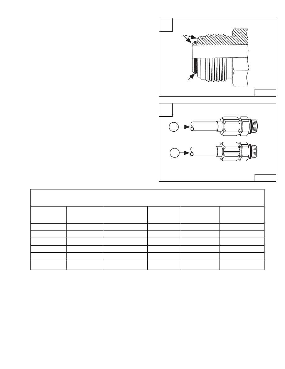
O–ring Flare Fitting
The flare is the primary seal, the O–ring is the secondary
seal and helps absorb vibration and pressure pulses at
the connection [A].
If necessary, the O–ring–flare fitting can be used without
an O–ring.
Use the following procedure to tighten the O–ring flare
fitting.
Tighten the nut until it contacts with the seat. Make a mark
across the flats of both the male and female parts of the
connection (Item 1) [B].
Use the chart below to find the correct tightness needed
(Item 2) [B]. If the fitting leaks after tightening, disconnect
it and inspect the seat area for damage.
* If a torque wrench is used to tighten a new fitting to a
used hose/tubeline.
* If a torque wrench is used to tighten a used fitting to a
new hose/tubeline.
* If a torque wrench is used to tighten a new fitting to a
new hose/tubeline.
Revised May 98
Tubeline
TORQUE
NEW
RE–ASSEMBLY
Outside
Ft.–lbs.
Rotate No.
Rotate No.
Wrench Size
Diameter
Thread Size
(Nm)
of Hex Flats
of Hex Flats
5/8’’
5/16’’
1/2’’ – 20
17 (23)
2–1/2
1
11/16’’
3/8’’
9/16’’ – 18
22 (30)
2
1
7/8’’
1/2’’
3/4’’ – 16
40 (54)
2
1
1’’
5/8’’
7/8’’ – 14
60 (81)
1–1/2
1
1–1/4’’
3/4’’
1–1/16’’ – 12
84 (114)
1
3/4
1–3/8’’
1’’
1–5/16’’ – 12
118 (160)
3/4
3/4
O–ring Flare Fitting Tightening Torque
**
***
*
**
If using the hex flat tightening method to tighten a new
fitting to a new hose/tubeline.
**
If using the hex flat tightening method to tighten a new
fitting to a used hose/tubeline.
***
If using the hex flat tightening method to tighten a used
fitting to a new hose/tubeline.
B
TS–01619
1
2
Hex Flat Tightening Method
773 BICS Loader
–9–11–
Service Manual
A
P–13009
O–ring Flare
Primary
Seal
Secondary
Seal
HYDRAULIC CONNECTION SPECIFICATIONS
(Cont’d)
O–ring Flare Fitting (Cont’d)
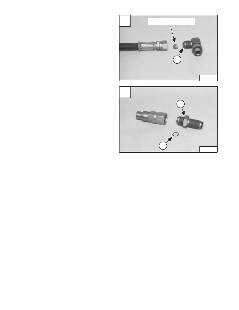
NOTE: O–ring flare fittings are not recommended in
all applications. Use the standard flare
fittings in these applications.
Do not use a O–ring flare fitting when a copper bonnet
orifice is used. When tightened the connection at the
bonnet may distort the flare face and prevent it from
sealing.
Use a standard flare fitting (Item 1) [A] as shown.
When a O–ring flare fitting is used as a straight thread port
adapter the O–ring flare face is not used to seal. The
O–ring may come off the fitting and enter the system.
Always remove the O–ring (Item 1) [B] from the flare
face as shown.
An O–ring (Item 2) [B] is added to the flat boss of the
fitting to seal the connection in this application.
Revised May 98
A
P–13572
Copper Bonnet Orifice
1
–9–12–
773 BICS Loader
Service Manual
B
P–13573
2
1
A
P–13008
Nut Seals
to Fitting
Nut Seals
to Port
Secondary O–ring Seal
HYDRAULIC CONNECTION SPECIFICATIONS
(Cont’d)
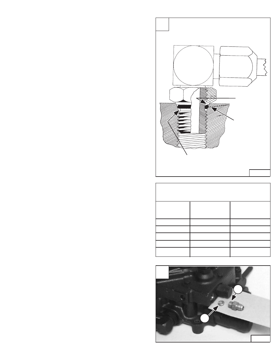
Port Seal Fitting
The nut is the primary seal, the O–ring is the secondary
seal and helps absorb vibration and pressure pulses at
the connection [A].
The hex portion of the nut does not contact the surface of
the component when the nut is tight.
Use the following procedure to tighten the port seal fitting:
Port seal and nut, washer and O–ring (O–ring Boss)
fittings use the same tightening torque valve chart.
If a torque wrench cannot be used, use the following
method.
Tighten the nut until it just makes metal to metal contact,
you can feel the resistance.
Tighten the nut with a wrench no more than one hex flat
maximum.
Do not over tighten the port seal fitting.
NOTE: If a torque wrench cannot be used, use the
hex flat tightening method as an approximate
guideline.
Revised May 98
NOTE: Port seal fittings are not recommended in all
applications. Use O–ring boss fittings in
these applications.
Do not use port seal fittings when a thread in orifice (Item
1) [B] is used in the port. The orifice may interfere with the
fitting and prevent it from sealing.
Use an O–ring boss fitting (Item 1) [B] as shown.
Fitting
TORQUE
Nut
Ft.–lbs.
Wrench Size
Thread Size
(Nm)
11/16’’
9/16’’ – 18
22 (30)
15/16’’
3/4’’ – 16
40 (54)
1–1/8’’
7/8’’ – 14
60 (81)
1–1/4’’
1–1/16’’ – 12
84 (114)
1–1/2’’
1–5/16’’ – 12
118 (160)
Port Seal and O–ring Boss
Tightening Torque
2
1
B
P–13571
773 BICS Loader
–9–13–
Service Manual
HYDRAULIC/HYDROSTATIC FLUID SPECIFICATIONS
Specifications
Use Bobcat hydraulic/hydrostatic transmission fluid (P/N 6563328). If this fluid is not
available, use 10W–30 or 10W–40 SAE Motor Oil (5W–30 for 0
°
F [–18
°
C] and
Below).
DO NOT use automatic transmission fluids in the loader or permanent damage to the
transmission will result.
Diesel fuel or hydraulic fluid under
pressure can penetrate skin or eyes,
causing serious injury or death.
Fluid leaks under pressure may not
be visible. Use a piece of cardboard
or wood to find leaks. Do not use
your bare hand. Wear safety
goggles. If fluid enters skin or eyes,
get immediate medical attention
from a physician familiar with this
injury.
W–2072–0496
When temperatures below zero degree F (–18
°
C) are common, the loader must be
kept in a warm building. Extra warm–up time must be used each time the loader is
started during cold temperature conditions. Cold fluid will not flow easily and it makes
action of the hydraulic function slower. Loss of fluid flow to the hydrostatic
transmission pump (indicated by TRANS light ON) can cause transmission damage
in less than 60 seconds.
During cold weather 32
°
F (0
°
C) and
below, do not operate machine until
the engine has run for at least five (5)
minutes at less than half throttle.
This warm–up period is necessary
for foot pedal operation and safe
stopping. Do not operate controls
during warm–up period. When
temperatures are below –20
°
F
(30
°
C), the hydrostatic oil must be
heated or kept warm. The
hydrostatic system will not get
enough oil at low temperatures. Park
the machine in an area where the
temperature will be above 0
°
F
(–18
°
C), if possible.
W–2027–1285
Revised June 01
–9–14–
773 BICS Loader
Service Manual
Нет комментариевНе стесняйтесь поделиться с нами вашим ценным мнением.
Текст