Loader Bobcat 773. Manual — part 122
D
N–17273
1
2
HYDRAULIC CONTROL VALVE (Cont’d)
Disassembly And Assembly
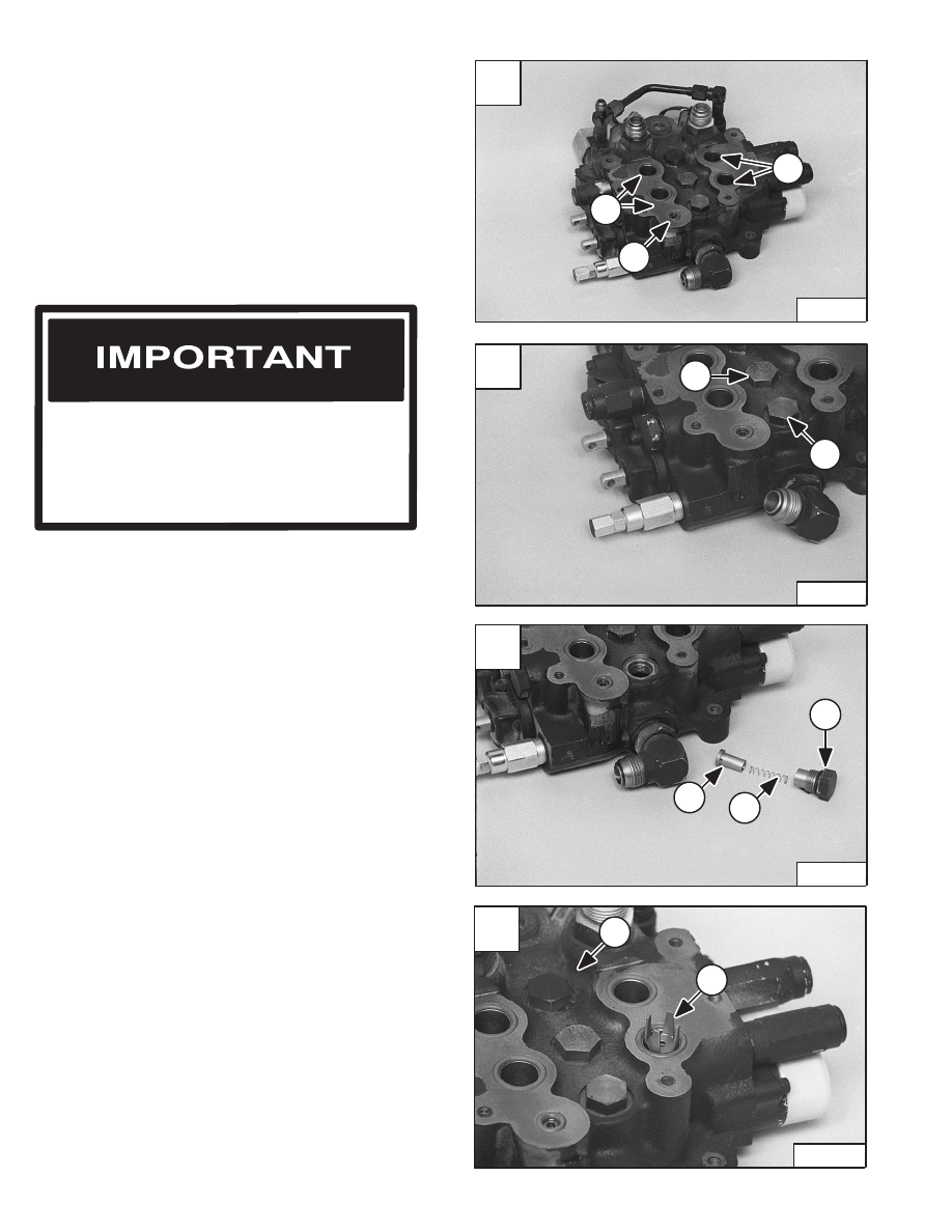
Remove the BICS valve assembly from the control valve.
(See Page 10–49.)
Remove the four large O–rings (Item 1) [A] and small
O–ring (Item 2) [A]. Always replace these O–rings before
installing the BICS valve assembly.
The anti–cavitation valve, port relief valves and plugs are
at different locations in the control valve. Refer to Control
Valve Identification Chart for the correct location of the
parts. (See Page 10–51.)
Mark each valve section, spool and related parts so that
they will be returned to its original valve location during
assembly.
Load Check Valve
Loosen the load check valve plug (Item 1) [B].
Installation: Always use new O–ring. Tighten the plug to
35–40 ft.–lbs. (47–54 Nm) torque.
Remove the load check plug (Item 1) [C].
Remove the spring (Item 2) [C] and poppet (Item 3) [C].
The auxiliary section (Item 1) [D] uses an orifice load
check poppet.
Lift Base End Restrictor
Remove the restrictor (Item 2) [D] from the lift section
base end port.
Check for damage and replace as needed.
When repairing hydrostatic and hydraulic
systems, clean the work area before
disassembly and keep all parts clean. Always
use caps and plugs on hoses, tubelines and
ports to keep dirt out. Dirt can quickly damage
the system.
I–2003–0888
A
N–17275
1
1
2
C
N–17274
1
2
3
–10–52–
Service Manual
773 BICS Loader
Revised Nov. 01
B
N–17276
1
1
HYDRAULIC CONTROL VALVE (Cont’d)
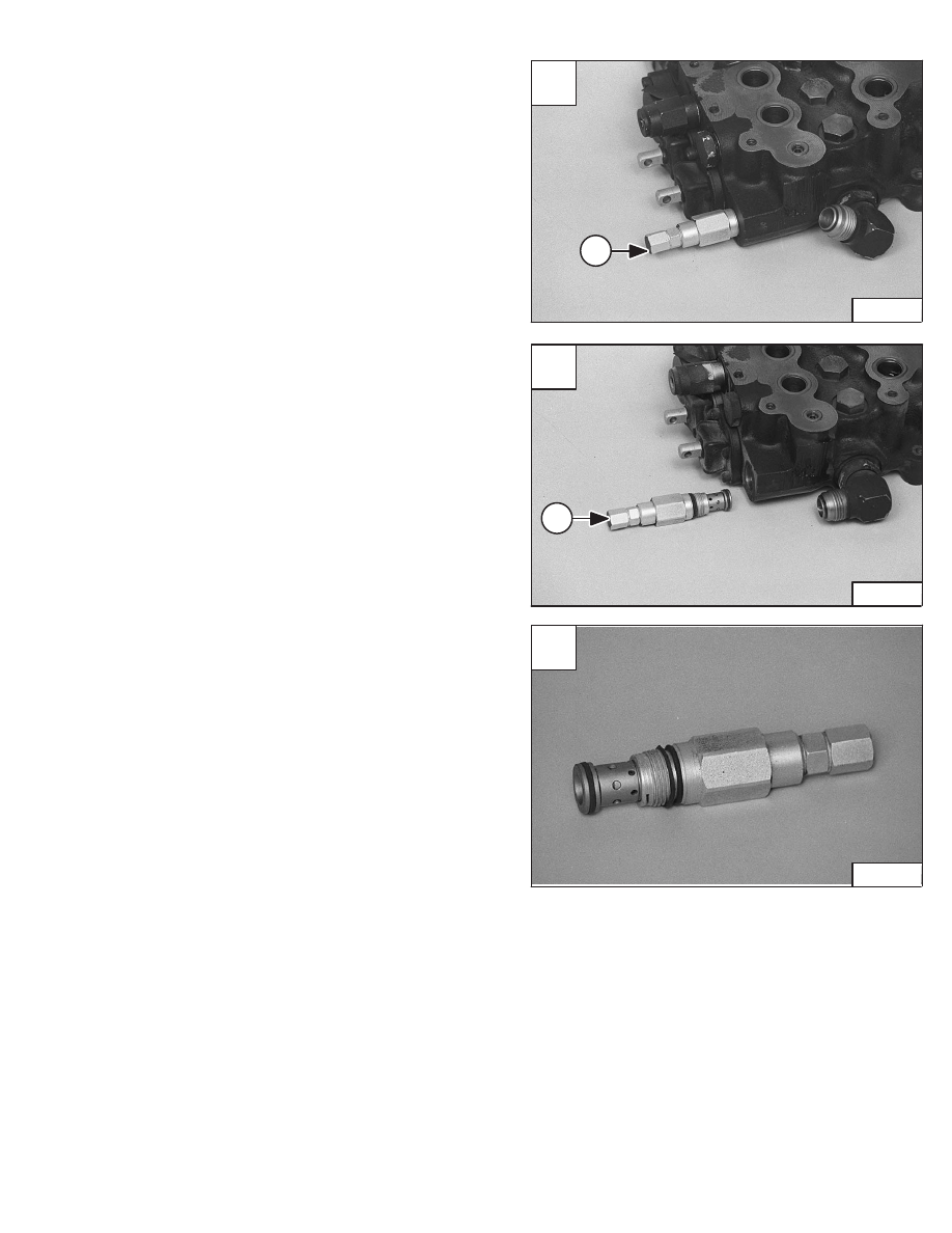
Main Relief Valve
Loosen the main relief valve (Item 1) [A].
Installation: Tighten the main relief to 35–40 ft.–lbs.
(47–54 Nm) torque.
Remove the main relief valve (Item 1) [B] from the control
valve.
Remove the O–rings, sleeve, and glide ring from the main
relief valve [C].
Installation: Always use new O–rings. sleeve, and glide
ring.
NOTE: See Page 2–1 for setting the pressure at the
main relief valve after the control valve is
installed in the loader.
C
N–17297
A
N–17276
1
Service Manual
–10–53–
773 BICS Loader
Revised Nov. 01
B
N–17272
1

HYDRAULIC CONTROL VALVE (Cont’d)
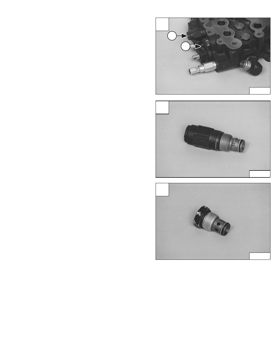
Port Relief Valve (Lift)
Loosen the port relief valve (Item 1) [A] (Port E1).
Installation: Tighten port relief to 35–40 ft.–lbs. (47–54
Nm) torque.
Remove the port relief valve from the control valve [B].
Remove the O–rings and back–up washer from the port
relief valve.
Installation: Always use new O–rings and back–up
washers.
Anti–Cavitation/Port Relief Valve
Loosen the anti–cavitation valve/port relief (Item 2) [A]
(Port E2).
Installation: Tighten cartridge to 35–40 ft.–lbs. (47–54
Nm) torque.
Remove the anti–cavitation valve/port relief from the
control valve [C].
Remove the O–rings and back–up washer from the
anti–cavitation/port relief.
Installation: Always use new O–rings and back–up
washers.
C
N–17285
A
N–17283
1
2
–10–54–
Service Manual
773 BICS Loader
Added June 01
B
N–17284
HYDRAULIC CONTROL VALVE (Cont’d)
Port Relief Valve (Tilt)
Loosen the port relief valve (Item 1) [A] (Port F2).
Installation: Tighten the anti–cavitation/port relief valve
to 35–40 ft.–lbs. (47–54 Nm) torque.
Remove the port relief from the control valve [B].
Remove the O–rings from the port relief valve.
Installation: Always use new O–rings and back–up
washers.
Anti–Cavitation Valve
Loosen the anti–cavitation valve (Item 2) [A] (Port F1).
Installation: Tighten the anti–cavitation valve to 35–40
ft.–lbs. (47–54 Nm) torque.
Remove the anti–cavitation valve from the control valve
[C].
Remove the O–rings from the anti–cavitation valve.
Installation: Always use new O–rings and back–up
washers.
A
N–17276
1
2
B
N–17278
Service Manual
–10–55–
773 BICS Loader
Added June 01
C
N–17277
Нет комментариевНе стесняйтесь поделиться с нами вашим ценным мнением.
Текст