Loader Bobcat 773. Manual — part 46
HYDROSTATIC PUMP (Cont’d)
Removal And Installation (Cont’d)
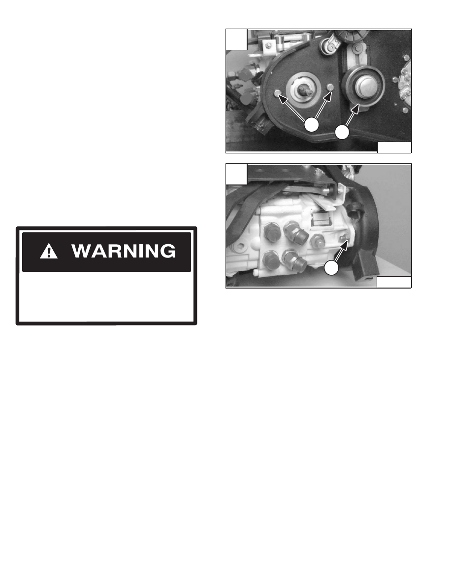
Installation: Install the key in the hydrostatic pump shaft
(Item 1) [A] before installing the pump drive pulley.
Hold the nut (Item 1) [B] on the two hydrostatic pump
mounting bolts (Item 2) [A].
Remove the two hydrostatic pump mounting bolts (Item
2) [A] from the pump and drive belt housing.
Installation: Tighten the pump mounting bolts to 65–70
ft.–lbs. (88–95 Nm) torque.
Reverse the removal procedure to install the hydrostatic
pump assembly.
Always clean up spilled fuel or oil. Keep heat,
flames, sparks or lighted tobacco away from
fuel and oil. Failure to use care around
combustibles can cause explosion or fire
which can result in injury or death.
W–2103–1285
A
P–04238
2
1
–3–36–
773 BICS Loader
Service Manual
B
P–04277
1
D–01929
1
2
3
4
5
6
7
8
13
10
9
21
17
18
14
12
9
34
35
36
39
38
41
45
42
29
27
26
12
23
24
22
49
43
47
25
48
25
23
26
24
22
16
16
15
15
13
19
20
17
18
11
14
40
45
32
30
46
44
20
23
22
24
27
33
21
21
28
29
25
26
32
31
25
28
23
26
22
38
37
34
36
9
10
15
11
14
17
21
18
18
17
9
51
52
6
5
1
16
16
35
24
30
1514
D–01979
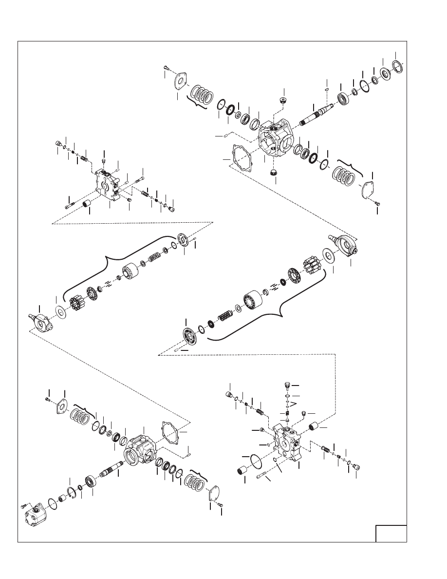
HYDROSTATIC PUMP (Cont’d)
Identification
MODEL: 773
50
–3–38–
773 BICS Loader
Service Manual
HYDROSTATIC PUMP (Cont’d)
Identification (Cont’d)
Ref.
Description
Ref.
Description
1.
SNAP RING
28.
PLUG
2.
ADAPTER
29.
BOLT
3.
SEAL
30.
RELIEF/REPLENISHING VALVE
4.
O–RING
31.
END CAP
5.
SNAP RING
32.
BEARING
6.
BEARING
33.
BOLT
7.
KEY
34.
SWASHPLATE
8.
SHAFT
35.
THRUST PLATE
9.
BOLT
36.
BLOCK ASSY.
10.
COVER
37.
VALVE PLATE
11.
SEAL
38.
PIN
12.
COVER
39.
VALVE PLAT
13.
PLUG
40.
PLUG
14.
QUAD RING
41.
O–RING
15.
SPACER
42.
SHIMS
16.
SHIMS (not used on later pumps)
43.
SPRING
17.
RACE
44.
CHARGE RELIEF
18.
BEARING
45.
PLUG
19.
HOUSING
46.
O–RING
20.
GASKET
47.
O–RING
21.
PIN
48.
END CAP
22.
PLUG
49.
O–RING
23.
O–RING
50.
COUPLING
24.
O–RING
51.
HOUSING
25.
SPRING
52.
SHAFT
26.
SNAP RING
27.
REPLENISHING VALVE (S/N 509641106
& Below, S/N 509616589 & Below)
RELIEF/REPLENISHING VALVE (S/N 509641107
& Above, S/N 509616590 & Above)
MODEL: 773
773 BICS Loader
–3–39–
Service Manual
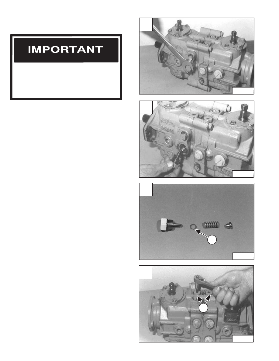
HYDROSTATIC PUMP (Cont’d)
Disassembly And Assembly
NOTE: Keep the two pump sections separate during
disassembly and assembly.
Loosen the charge relief valve plug [A].
Assemble: Always use a new O–ring. Tighten the plug to
30–50 ft.–lbs. (41–68 Nm) torque.
Remove the plug, spring and poppet [B].
There are several different thickness of the shims (Item
1) [C] and are used to adjust the charge pressure.
NOTE: Photo’s may be different but the procedure is
the same for all models.
NOTE: S/N 509641107 & Above and S/N 509616590 &
Above now use relief/replenishing valves
(Item 1) [D]. The relief valve limits the
pressure in the motor drive circuit when
operating in reverse.
NOTE: The relief valve on the top of the pump is for
the reverse circuit, the bottom relief valve on
the pump is for the forward circuit and is set
at 5000 PSI.
When repairing hydrostatic and hydraulic
systems, clean the work area before
disassembly and keep all parts clean. Always
use caps and plugs on hoses, tubelines and
ports to keep dirt out. Dirt can quickly damage
the system.
I–2003–0888
Loosen the replenishing valve plug [D].
Assemble: Always use a new O–ring. Tighten the plug to
30–50 ft.–lbs. (41–68 Nm) torque.
NOTE: 0.010 inch (0,254 mm) is 8 PSI (55.16 kPa)
increase in pressure.
A
CD–10745
C
N–00961
1
D
CD–10748
1
–3–40–
773 BICS Loader
Service Manual
B
CD–10746
Нет комментариевНе стесняйтесь поделиться с нами вашим ценным мнением.
Текст