Loader Bobcat 773. Manual — part 11

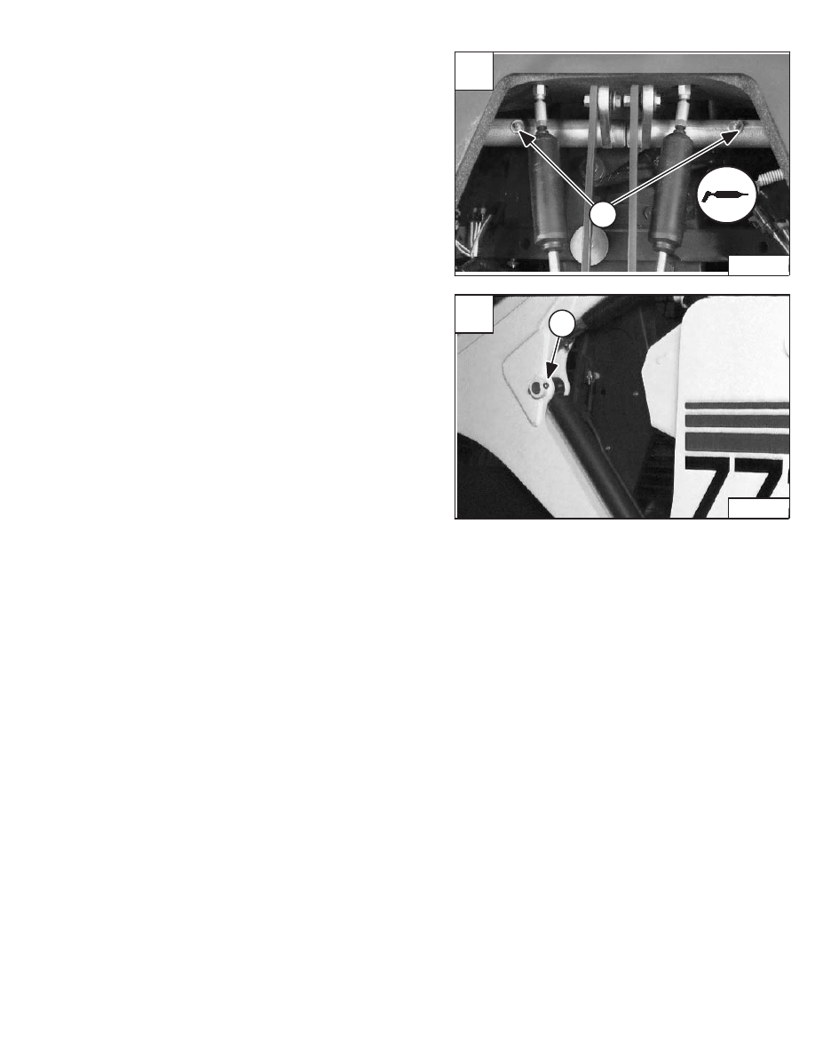
6. Tilt Cylinder Rod End. [A].
7. Bob–Tach Wedge (Both Sides) [B].
8. Bob–Tach Pivot Pin (Both Sides) [C].
9. Lift Arm Pivot Pin (Both Sides) [D].
10. Lift Arm Link Pivot Pin (Both Sides) [D].
LUBRICATION OF THE BOBCAT LOADER (Cont’d)
Revised Jan. 99
6
A
P–10625
8
C
P–10635
9
D
P–10621
10
–1–34–
773 BICS Loader
Service Manual
7
B
P–10626
LUBRICATION OF THE BOBCAT LOADER (Cont’d)
11. 250 Hours: Steering Lever Shaft (2) [A].
PIVOT PINS
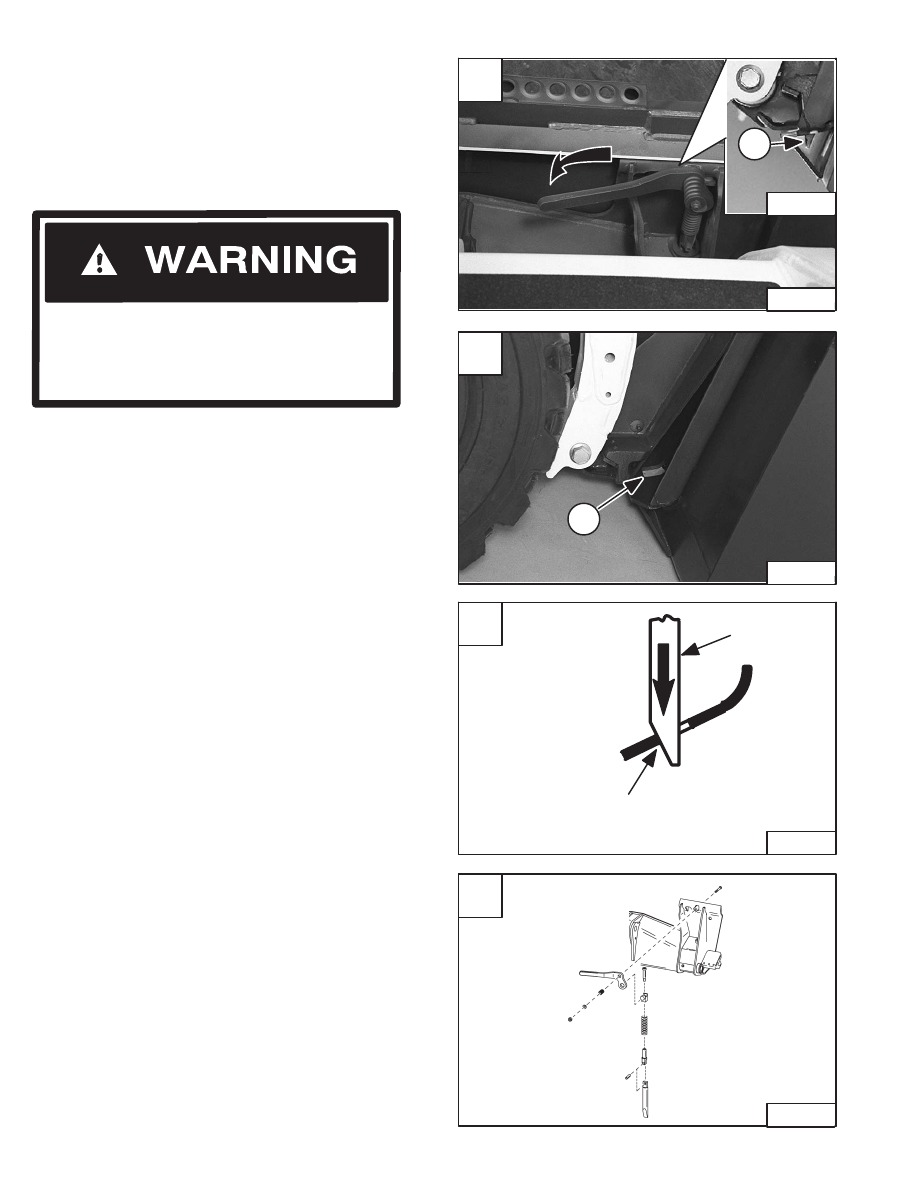
All lift arm and cylinder pivots have a large pin held in
position with a retainer bolt and lock nut (Item 1) [B].
Check that the lock nuts are tightened to 18–20 ft.–lbs.
(24–27 Nm) torque.
Revised Jan. 99
A
P–01533
11
773 BICS Loader
–1–35–
Service Manual
B
P–10620
1
BOB–TACH
Inspection and Maintenance
Move the Bob–Tach levers to engage the wedges [A].
The levers and wedges must move freely.
The wedges must extend through the holes in the
attachment mounting frame (Item 1) [A].
The spring loaded wedge (Item 1) [A] must contact the
lower edge of the hole in the attachment (Item 1) [B] and
[C].
If the wedge does not contact the lower edge of the hole
[B] and [C], the attachment will be loose and can come
off the Bob–Tach.
Inspect the mounting frame on the attachment and the
Bob–Tach, linkages and wedges for excessive wear or
damage [D]. Replace any parts that are damaged, bent,
or missing. Keep all fasteners tight.
Look for cracked welds. Contact your Bobcat dealer for
repair or replacement parts.
Lubricate the wedges (See SERVICE SCHEDULE, Page
1–3 and LUBRICATION OF THE BOBCAT LOADER,
Page 1–33).
Revised June 01
Bob–Tach wedges must extend through the
holes in attachment. Levers must be fully
down and locked. Failure to secure wedges
can allow attachment to come off and cause
injury or death.
W–2102–0588
A
N–17027
N–17022
1
–1–36–
773 BICS Loader
Service Manual
D
TS–01062
C
Bob–Tach
Wedge
Wedge Must Contact
Lower Edge Of Hole
In The Attachment
B–15177
B
1
N–17023
REMOTE START SWITCH
Procedure
The tool listed will be needed to do the following
procedure:
MEL1429 – Remote Start Switch
Put jackstands under the front axles and rear
corners of the frame before running the engine
for service. Failure to use jackstands can allow
the machine to fall or move and cause injury or
death.
W–2017–0286
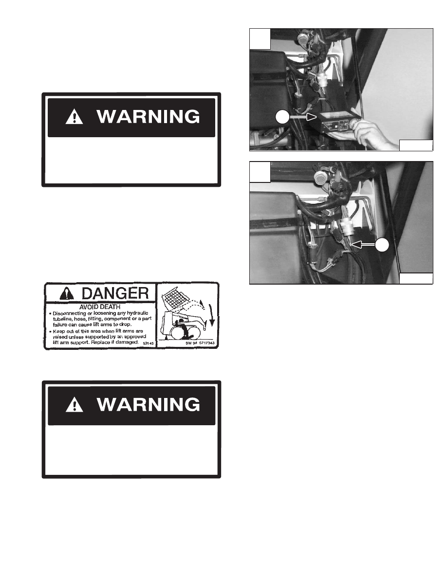
The Remote Start Switch (Item 1) [A] is required when the
operator cab is in the raised position for service and the
service technician needs to start the engine. The operator
cab wire harness connectors must be separated from the
engine wiring harness connector under the cab.
The remote start switch is required when the service
technician is adjusting the steering linkage and checking
the hydraulic/hydrostatic system.
Lift and block the loader. (See Page 1–4.)
Raise the operator cab. (See Page 1–9.)
Connect the remote start switch to these connectors
(Item 1) [B].
Never work on a machine with the lift arms up
unless the lift arms are secured by an approved
lift arm support device. Failure to use an
approved lift arm support device can allow the
lift arms or attachment to fall and cause injury
or death.
W–2059–0598
Revised Jan. 99
Raise the lift arms and install an approved lift arm support
device. (See Page 1–7.)
A
P–10115
1
773 BICS Loader
–1–37–
Service Manual
B
P–10114
1
Нет комментариевНе стесняйтесь поделиться с нами вашим ценным мнением.
Текст