Loader Bobcat 773. Manual — part 34

HYDRAULIC PUMP (Cont’d)
Disassembly And Assembly (Cont’d)
Remove the other end bearing housing [A].
NOTE: Always use new O–rings and seals when
assembling the hydraulic pump.
Inspection
Wash all parts in clean solvent and use air pressure to dry
them.
Make a visual inspection of all the parts. If parts are visibly
worn or damaged, pump replacement is necessary.
Check the gear [B]. If excessive wear is visible on the
journals, side or face of the gears they must be replaced.
If the splines are worn, replace the drive gear.
Check the bushings in the housing [B]. Replace the
bushings as needed.
Identification
A
CD–10743
TS–01022
1
2
3
4
5
6
7
8
10
9
8
6
5
12
11
2
4
13
MODEL: 773
1. BOLT
2. WASHER
3. END HOUSING
4. O–RING SEAL
5. SEAL
6. RING
7. BODY
8. BEARING HOUSING
9. DRIVE GEAR
10. IDLER GEAR
11. DOWEL
12. END HOUSING
13. O–RING
–2–82–
773 BICS Loader
Service Manual
B
CD–10744
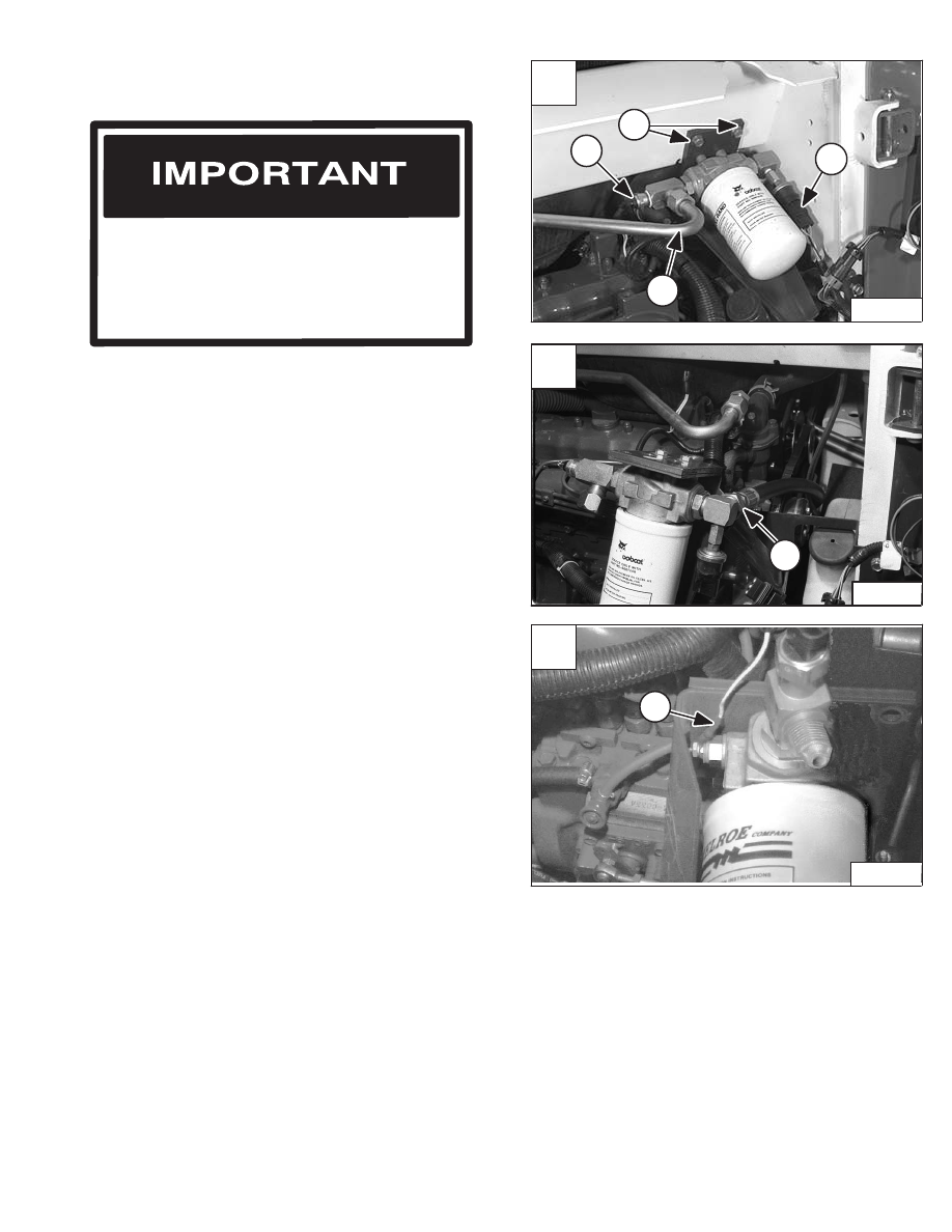
HYDRAULIC FILTER HOUSING
Removal And Installation
Disconnect the temperature sender connector (Item 2)
[A] from the filter housing.
Disconnect the oil cooler tubeline (Item 3) [A] from the
filter housing.
Remove the two mounting bolts (Item 4) [A] from the filter
housing mounting bracket.
Installation: Tighten the mounting bolts to 25 ft.–lbs. (34
Nm) torque.
Disconnect the hose (Item 1) [B] from the filter housing
outlet.
Disconnect the wire (Item 1) [C] from the differential
pressure switch on the filter housing.
Remove the hydraulic filter housing and filter.
Reverse the removal procedure to install the filter housing
and filter.
When repairing hydrostatic and hydraulic
systems, clean the work area before
disassembly and keep all parts clean. Always
use caps and plugs on hoses, tubelines and
ports to keep dirt out. Dirt can quickly damage
the system.
I–2003–0888
Stop the engine and open the rear door.
Remove the muffler. (See Page 7–1.)
Disconnect the wires from the charge pressure sender
(Item 1) [A] from the filter housing.
Revised May 98
A
P–11784
3
2
1
4
C
P–04207
1
773 BICS Loader
–2–83–
Service Manual
B
N–15399
1
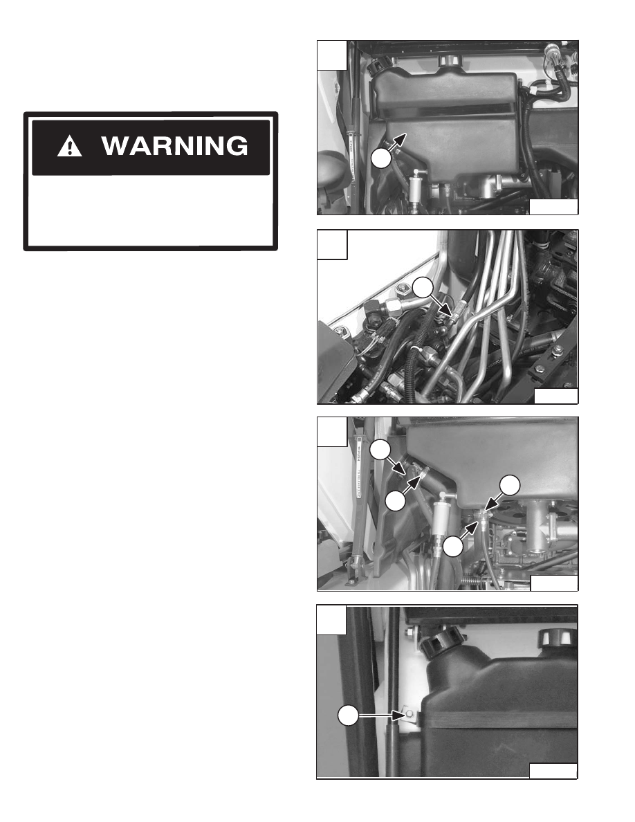
HYDRAULIC FLUID RESERVOIR
Removal And Installation
Raise the lift arms and install an approved lift arm support
device. (See Page 1–1.)
Disconnect the case drain hose (Item 1) [B] from main
control valve.
Place the end of hose in a clean container and drain the
fluid from the reservoir.
Disconnect the fuel fill hose (Item 1) [C], fuel tank
breather hose (Item 2) [C].
Disconnect the hydraulic pump inlet hose (Item 3) [C]
from the reservoir.
Disconnect the tubeline (Item 4) [C] from the reservoir
which comes from the tilt lock valve.
Remove the right side mounting bolt (Item 1) [D] and plate
from the mounting strap.
Installation: Tighten the bolt to 16–20 ft.–lbs. (22–27
Nm) torque.
Remove the hydraulic reservoir from the loader.
Reverse removal procedure to install the hydraulic fluid
reservoir.
Refer to the loader specification section for the correct
hydraulic fluid capacity.
Raise the operator cab. (See Page 1–1.)
Hydraulic fluid reservoir is located behind the operator
cab mounted on the loader frame (Item 1) [A].
Revised May 98
Never work on a machine with the lift arms up
unless the lift arms are secured by an approved
lift arm support device. Failure to use an
approved lift arm support device can allow the
lift arms or attachment to fall and cause injury
or death.
W–2059–0598
A
N–00808
1
C
N–00809
4
3
1
2
D
P–04067
1
–2–84–
773 BICS Loader
Service Manual
1
B
P–11779
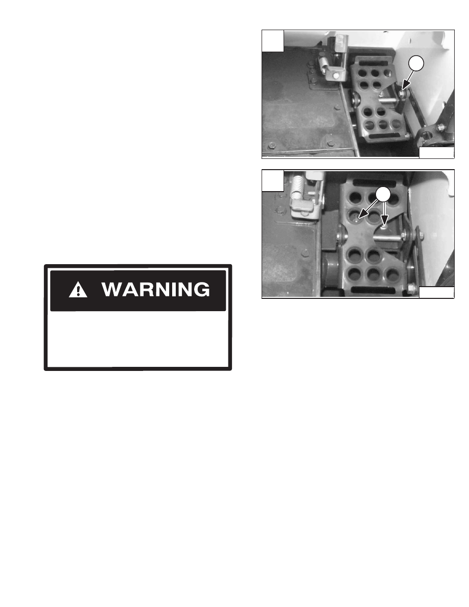
CONTROL PEDALS
Removal And Installation
Remove the bolt (Item 1) [A] and nut from the pedal
linkage.
Installation: Tighten the bolt and nut to 21–25 ft.–lbs.
(28–34 Nm) torque.
Check the rubber bushing in the pedal for wear and
replace as needed.
Remove the two mounting bolts (Item 1) [B] from the
pedal mounting bracket.
Remove the pedal assembly from the loader.
Pedal Adjustment
After installing the pedal, adjust the pedal so that there is
clearance under the rear of the pedal. The valve spool
must travel full stroke without the pedal hitting the floor
panel.
NOTE: See Page 2–87 for correct procedure to
adjust the pedal interlock linkage.
W–2104–0199
Adjust locking tabs on control linkage so that
lift and tilt control pedals or (Mechanical Hand
Controls) are locked in neutral when the seat
bar is up.
AVOID INJURY OR DEATH
Revised June 01
A
P–04059
1
773 BICS Loader
–2–85–
Service Manual
B
P–04061
1
Нет комментариевНе стесняйтесь поделиться с нами вашим ценным мнением.
Текст