Loader Bobcat 773. Manual — part 18
HYDRAULIC CYLINDERS (Cont’d)
Assembly (Cont’d)
Clean and dry the cylinder rod threads.
For the tilt cylinder only:
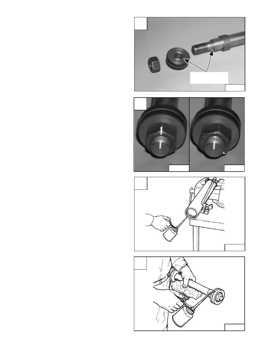
Apply grease to the shoulder of the rod shaft where the
piston makes contact [A]. Do not get grease on the
threads.
For lift and tilt cylinders:
Install the piston (with the chamfered side to the cylinder
rod shoulder) and the nut.
Tighten the lift cylinder nut (with 0.750 inch thread
diameter) to 180 ft.–lbs. (244 Nm) torque.
For tilt cylinder only:
Grease the piston where the nut contacts the piston. Do
not get grease on the threads.
Tighten the nut (with 1.125 inch thread diameter) to 100
ft.–lbs. (136 Nm) torque.
Mark the end of the shaft and nut [B]. Tighten the nut an
additional 135 degrees or 2–1/4 flats [B].
For lift and tilt cylinders:
Remove the rod from the vise.
Install the cylinder case in the vise.
Put oil on the seal surface of the cylinder case [C].
Put oil on the teflon seal on the piston [D].
Revised May 98
D
B–07012
A
P–10452
Gease Shoulder
And Piston
C
B–07013
–2–18–
773 BICS Loader
Service Manual
B
P–10456
P–10450
HYDRAULIC CYLINDERS (Cont’d)
Assembly (Cont’d)
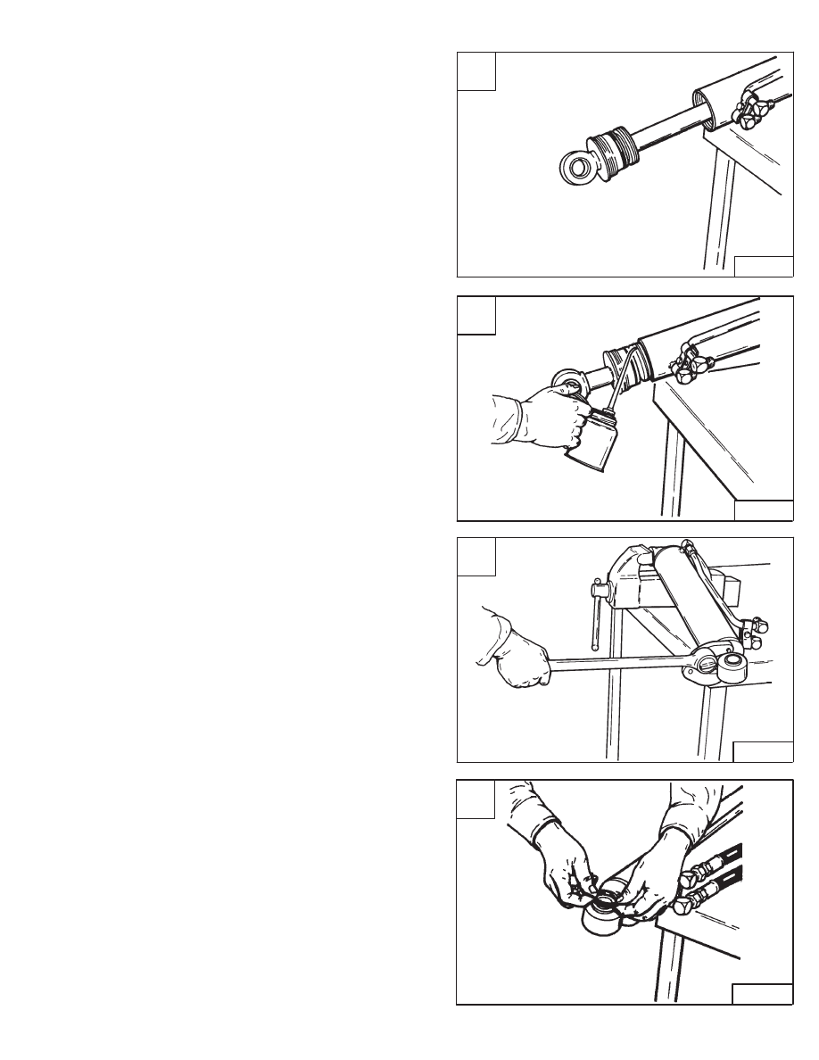
Install the rod assembly in the cylinder case [A].
Put oil on the seals on the head [B].
Put oil on the threads of the head.
Use the adjustable gland nut wrench to tighten the head
[C].
Replace the seal on the rod end (if so equipped) if it shows
signs of wear or damage[D].
A
B–07001
C
B–07000
D
B–07015
773 BICS Loader
–2–19–
Service Manual
B
B–07014
BICS
™
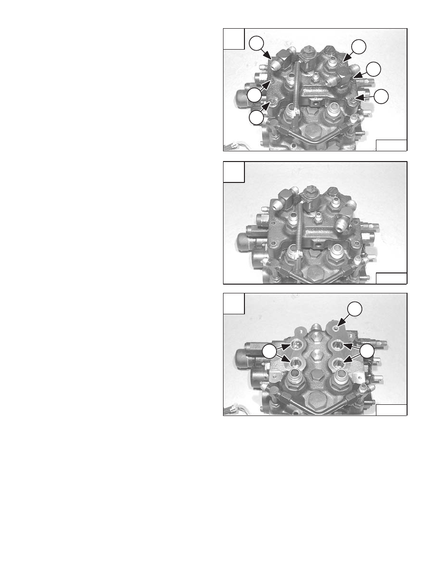
VALVE (S/N 509640660 & Above, S/N
509616542 & Above)
Removal
Remove the BICS
™
/control valve. (See Page 2–28.)
Loosen and remove the six mounting bolts (Item 1) [A].
Remove the BICS
™
valve assembly from the top of the
control valve [B].
Remove the four large O–rings (Item 1) [C] and the small
O–ring (Item 2) [C] from the top of the control valve.
A
P–08948
1
1
1
1
1
1
C
P–08950
2
1
1
–2–20–
773 BICS Loader
Service Manual
B
P–08949
BICS
™
VALVE (S/N 509640660 & Above, S/N
509616542 & Above) (Cont’d)
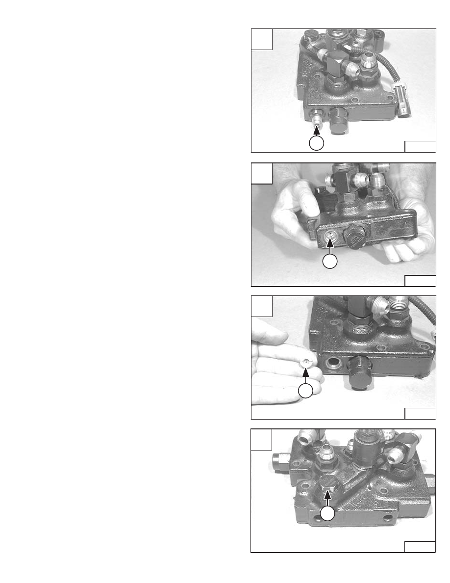
Lift Arm By–Pass Orifice
Disassembly
Remove the fitting (Item 1) [A] from the valve.
Using a flat blade screw driver, remove the lift arm
by–pass orifice (Item 1) [B] & [C].
Orifice size is 0.078 inch.
Check Valve
Disassembly
Remove the check valve (Item 1) [D].
A
P–08951
1
C
P–08953
1
D
P–08954
1
773 BICS Loader
–2–21–
Service Manual
B
P–08952
1
Нет комментариевНе стесняйтесь поделиться с нами вашим ценным мнением.
Текст