Bobcat S150. Manual — part 6

S150 Bobcat Loader
7
Operation & Maintenance Manual
INSTRUMENT PANEL IDENTIFICATION (CONT’D)
Option And Field Accessory Panels (If Equipped)
Figure 10
Figure 11
NOTE: Parking Brake (13) [Figure 11] is Standard on
all loaders.
Side Accessory Panel [Figure 10].
Front Accessory Panel [Figure 11]
P16000
SIDE ACCESSORY PANEL
3
1
2
4
5
6
7
8
9
B-15993B
OR
17
B-15993H
FRONT ACCESSORY PANEL
10
11
12
13
14
15
16
REF.
NO.
DESC.
FUNCTION / OPERATION
1
POWER PLUG Provides a 12V receptacle for
accessories.
2
NOT USED
- - -
3
FRONT
WIPER
Press the top of the switch to start the
front wiper (press and hold for washer
fluid). Press the bottom of the switch to
stop the wiper.
4
REAR WIPER
Press the bottom of the switch to start
the rear wiper. Press the top of the
switch to provide washer fluid to clean
the rear window.
5
NOT USED
- - -
6
NOT USED
- - -
7
FAN MOTOR
Turn clockwise to increase fan speed;
counterclockwise to decrease. There
are four positions; OFF-1-2-3.
8
AIR COND.
SWITCH
Press top of switch to start; bottom to
stop. Fan Motor (7) must be ON for A/C
to operate.
9
TEMP.
CONTROL
Turn clockwise to increase the
temperature; counterclockwise to
decrease.
REF.
NO.
DESC.
FUNCTION / OPERATION
10
ADVANCED
CONTROL
SYSTEM
(ACS)
Press the top to select Hand Controls;
bottom to select Foot Controls.
11
NOT USED
- - -
12
POWER
BOB-TACH
Press and hold the up arrow to
disengage the the Bob-Tach wedges.
Press and hold the down arrow to
engage the wedges into the mounting
frame holes.
13
PARKING
BRAKE
(Standard on
all Loaders)
Press the top to engage the PARKING
BRAKE; bottom to disengage.
14
TURN SIGNAL
INDICATORS
Indicates left or right TURN SIGNALS
are ON.
15
HAZARD
LIGHTS
Press the top to turn the HAZARD
LIGHTS ON; right side bottom to turn
OFF.
16
ROTATING
BEACON
Press the top to turn the ROTATING
BEACON ON; bottom to turn OFF.
17
SELECTABLE
JOYSTICK
CONTROL
(SJC)
Press the top to select ‘ISO’ Control
Pattern; bottom to select ‘H’ Control
Pattern.

S150 Bobcat Loader
Operation & Maintenance Manual
8
INSTRUMENT PANEL IDENTIFICATION (CONT’D)
Cab Light
Figure 12
Push the button (1) [Figure 12] to turn the light ON. Push
the button again to turn OFF.
LIFT ARM BY-PASS CONTROL
Operation
Figure 13
The lift arm by-pass control (1) [Figure 13] is used to
lower the lift arms if the lift arms cannot be lowered
during normal operations.
•
Sit in the operator’s seat.
•
Fasten the seat belt and lower the seat bar.
•
Turn the knob (1) [Figure 13] clockwise 1/4 turn.
•
Pull up and hold the knob until the lift arms slowly
lower.
TRACTION LOCK OVERRIDE
Operation
Figure 14
(Functions Only When The Seat Bar Is Raised And The
Engine Is Running) There is a TRACTION LOCK
OVERRIDE Button (1) [Figure 14] on the left instrument
panel which will allow you to use the steering levers to
move the loader forward and backward when using the
backhoe attachment or for loader service.
•
Press the TRACTION LOCK OVERRIDE button once
to unlock traction lock drive. The TRACTION light (2)
[Figure 14] will be ON.
•
Press the button a second time to lock the traction
drive. The TRACTION light (2) [Figure 14] will be
OFF.
N-22015
1
P-31863
1
1
B-15551
2
1
S150 Bobcat Loader
9
Operation & Maintenance Manual
ENGINE SPEED CONTROL
Operation
Figure 15
The speed control lever is at the right side of the
operator’s seat (1) [Figure 15].
Move the lever forward to increase engine speed. Move
backward to decrease engine speed.
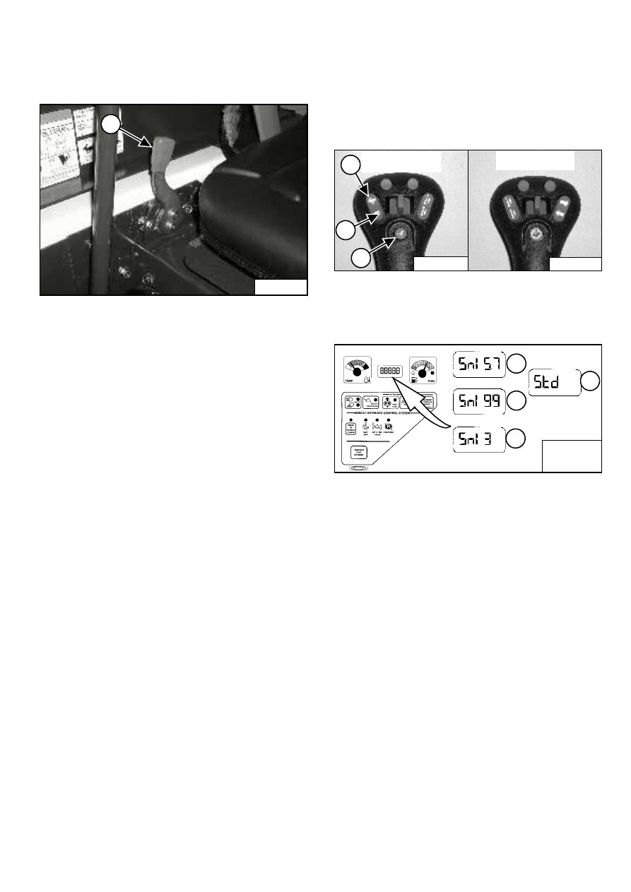
INCHING CONTROL
Operation
The Inching Control allows the loader to be maneuvered
at slow travel speed for installing attachments, loading or
unloading.
Figure 16
Press the button (1) [Figure 16] on the left joystick once
to engage the Inching Control.
Figure 17
When the Inching Control is engaged, the machine will
travel at 57% of Standard travel speed and the
percentage [Snl 57] will appear in the display (1)
[Figure 17].
While Inching Control is engaged, press the top of the
Speed Control switch (2) [Figure 16] to increase the
speed up to 99% [Snl 99] or the bottom of the switch (3)
[Figure 16] to decrease the speed down to 3% [Snl 3].
The percentages will appear in the display (1, 2 and 3)
[Figure 17].
Press button (1) [Figure 16] again to disengage Inching
Control and return to Standard Travel Speed ([Std] (4)
[Figure 17] will appear in display).
The system will retain the speed percentage as long as
the key remains ON (Standard Panel) or the STOP button
has not been pressed (Deluxe Panel).
EXAMPLE: You can be using the machine at 40%
and then disengage the Inching Control to
reposition the loader, then re-engage Inching
Control. The speed percentage will still be at 40%.
If you turn the key OFF or press the STOP button,
the next time you start the engine and engage the
Inching Control, the speed will be at 57% of
Standard Travel Speed.
P-31864
1
P-24802
Right Joystick
1
P-24820
Left Joystick
2
1
3
B-15551-1A
B-15551-1B
B-15551-1C
1
2
3
4
B-15551

S150 Bobcat Loader
Operation & Maintenance Manual
10
PARKING BRAKE
Operation
Figure 18
Press the top of the switch (1) [Figure 18] to engage the
parking brake. The traction drive system will be locked.
Press the bottom of the switch (2) [Figure 18] to
disengage the parking brake. The traction drive system
will be unlocked.
NOTE: The TRACTION light on the left instrument
panel will remain OFF until the engine is
started, the PRESS TO OPERATE LOADER
button is pressed and the parking brake is
disengaged.
B-15993
2
1
Нет комментариевНе стесняйтесь поделиться с нами вашим ценным мнением.
Текст