Bobcat S150. Manual — part 12
S150 Bobcat Loader
31
Operation & Maintenance Manual
ATTACHMENTS AND BUCKETS (CONT’D)
Pallet Forks
Figure 62
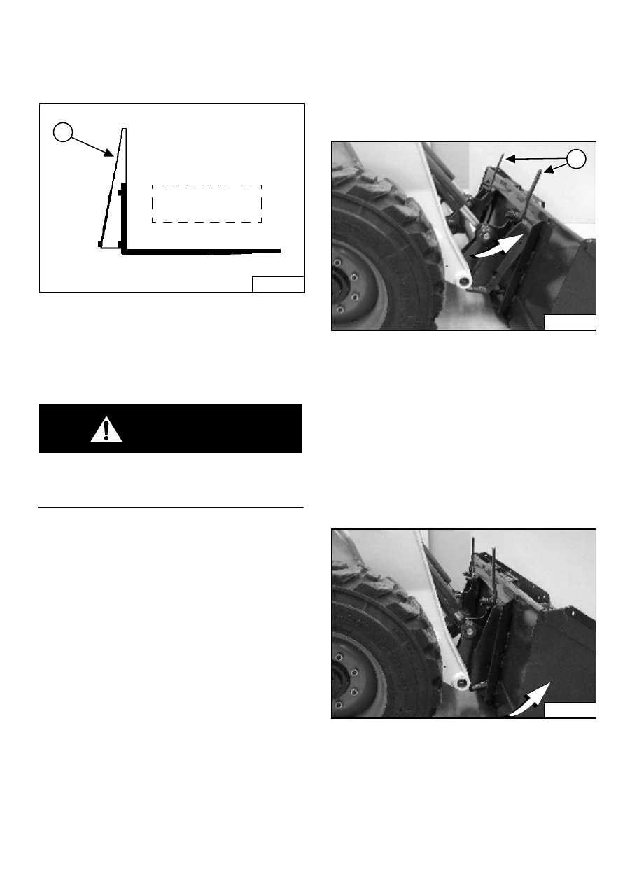
If a pallet fork attachment is used, the load center moves
forward and reduces the Rated Operating Capacity.
The maximum load to be carried when using a pallet fork
is shown on a decal located on the pallet fork frame (1)
[Figure 62].
WARNING
AVOID INJURY OR DEATH
Do not exceed Rated Operating Capacity. Excessive
load can cause tipping or loss of control.
W-2053-0903
See your Bobcat dealer for more information about pallet
fork inspection, maintenance and replacement. See your
Bobcat Loader dealer for Rated Operating Capacity when
using a pallet fork and for other available attachments.
Hand Lever Bob-Tach™ - Installing The Bucket Or
Attachment
The Bob-Tach is used for fast changing of buckets and
attachments. See the appropriate Attachment Operation
& Maintenance Manual to install other attachments.
Figure 63
Pull the Bob-Tach levers all the way up (1) [Figure 63].
Enter the loader and perform the PRE-STARTING
PROCEDURE. (See also PRE-STARTING PROCEDURES
on Page 22).
Lower the lift arms and tilt the Bob-Tach forward.
Drive the loader forward until the top edge of the Bob-
Tach is completely under the top flange of the bucket
[Figure 63] (or other attachment). Be sure the Bob-Tach
levers do not hit the bucket.
Figure 64
Tilt the Bob-Tach backward until the cutting edge of the
bucket (or other attachment) is slightly off the ground
[Figure 64].
Stop the engine and exit the loader.
B-17255
1
Load varies with
model of pallet fork
being used.
P-31238
1
P-31239
S150 Bobcat Loader
Operation & Maintenance Manual
32
ATTACHMENTS AND BUCKETS (CONT’D)
Hand Lever Bob-Tach™ - Installing The Bucket Or
Attachment (Cont’d)
WARNING
Before you leave the operator’s seat:
•
Lower the lift arms, put the attachment flat on the
ground.
•
Stop the engine.
•
Engage the parking brake.
•
Raise seat bar.
•
(Foot Pedal Controls) Move pedals until both
lock.
•
(Advanced Control System - ACS) Move the
hydraulic controls to the NEUTRAL POSITION to
make sure that both lift and tilt functions are
deactivated.
The seat bar system must deactivate the lift and
tilt control functions when the seat bar is up.
Service the system if hand controls do not
deactivate.
•
(Selectable Joystick Control - SJC) Move the
joysticks to the NEUTRAL POSITION to make
sure that travel and hydraulic functions are
deactivated.
The seat bar system must deactivate these
functions when the seat bar is up. Service the
system if controls do not deactivate.
W-2463-0603
Figure 65
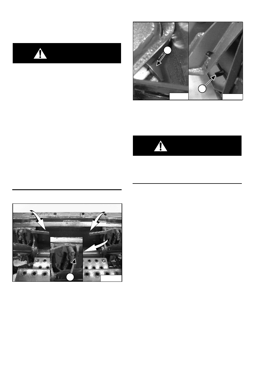
Push down on the Bob-Tach levers until they are fully
engaged in the locked position (1) [Figure 65] (wedges
fully extended).
Figure 66
The wedges (1) [Figure 66] must extend through the
holes (2) [Figure 66] in the mounting frame of the bucket
(or other attachment), securely fastening the bucket to
the Bob-Tach.
WARNING
Bob-Tach wedges must extend through the holes in
attachment. Levers must be fully down and locked.
Failure to secure wedges can allow attachment to
come off and cause injury or death.
W-2102-0588
P-31241
1
P-31233
1
P-31237
2
S150 Bobcat Loader
33
Operation & Maintenance Manual
ATTACHMENTS AND BUCKETS (CONT’D)
Hand Lever Bob-Tach™ - Removing The Bucket Or
Attachment
Lower the lift arms and put the attachment flat on the
ground.
Raise the seat bar, unfasten the seat belt, set the parking
brake and exit the loader.
If the attachment is hydraulically controlled, lower or
close the hydraulic equipment. You may need to release
hydraulic pressure before disconnecting the quick
couplers. (See Releasing Hydraulic Pressure (Loader
and Attachment) on Page 18.)
WARNING
Before you leave the operator’s seat:
•
Lower the lift arms, put the attachment flat on the
ground.
•
Stop the engine.
•
Engage the parking brake.
•
Raise seat bar.
•
(Foot Pedal Controls) Move pedals until both
lock.
•
(Advanced Control System - ACS) Move the
hydraulic controls to the NEUTRAL POSITION to
make sure that both lift and tilt functions are
deactivated.
The seat bar system must deactivate the lift and
tilt control functions when the seat bar is up.
Service the system if hand controls do not
deactivate.
•
(Selectable Joystick Control - SJC) Move the
joysticks to the NEUTRAL POSITION to make
sure that travel and hydraulic functions are
deactivated.
The seat bar system must deactivate these
functions when the seat bar is up. Service the
system if controls do not deactivate.
W-2463-0603
Figure 67
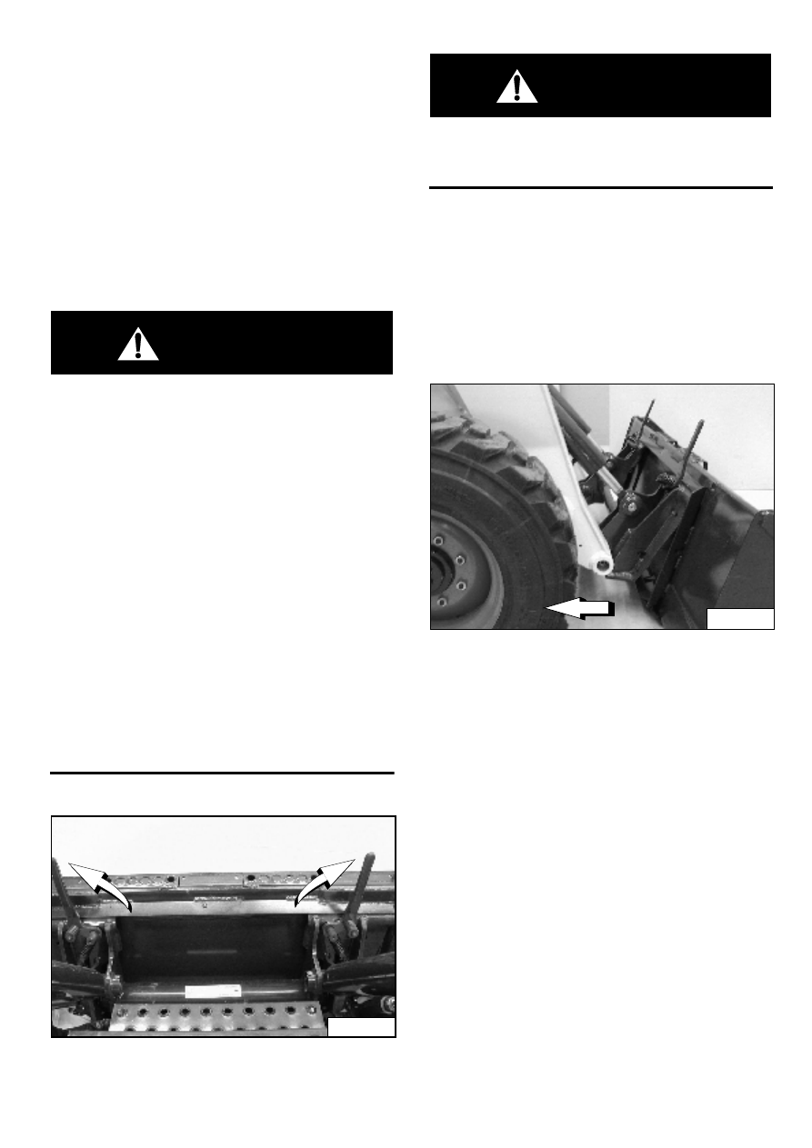
Pull the Bob-Tach levers [Figure 67] all the way up.
WARNING
Bob-Tach levers have spring tension. Hold lever
tightly and release slowly. Failure to obey warning
can cause injury.
W-2054-1285
Enter the loader.
Perform the PRE-STARTING PROCEDURE. (See PRE-
STARTING PROCEDURES on Page 22.)
Start the engine and release the parking brake.
Be sure the lift arms are all the way down. Tilt the
Bob-Tach forward.
Figure 68
Move the loader backward, away from the bucket or
attachment [Figure 68].
P-31240
P-31238
S150 Bobcat Loader
Operation & Maintenance Manual
34
ATTACHMENTS AND BUCKETS (CONT’D)
Power Bob-Tach™ - Installing The Bucket Or
Attachment
The Bob-Tach is used for fast changing of buckets and
attachments. See the appropriate Attachment Operation
& Maintenance Manual to install other attachments.
Perform the PRE-STARTING PROCEDURE. (See PRE-
STARTING PROCEDURES on Page 22.)
Lower the lift arms and tilt the Bob-Tach forward.
Figure 69
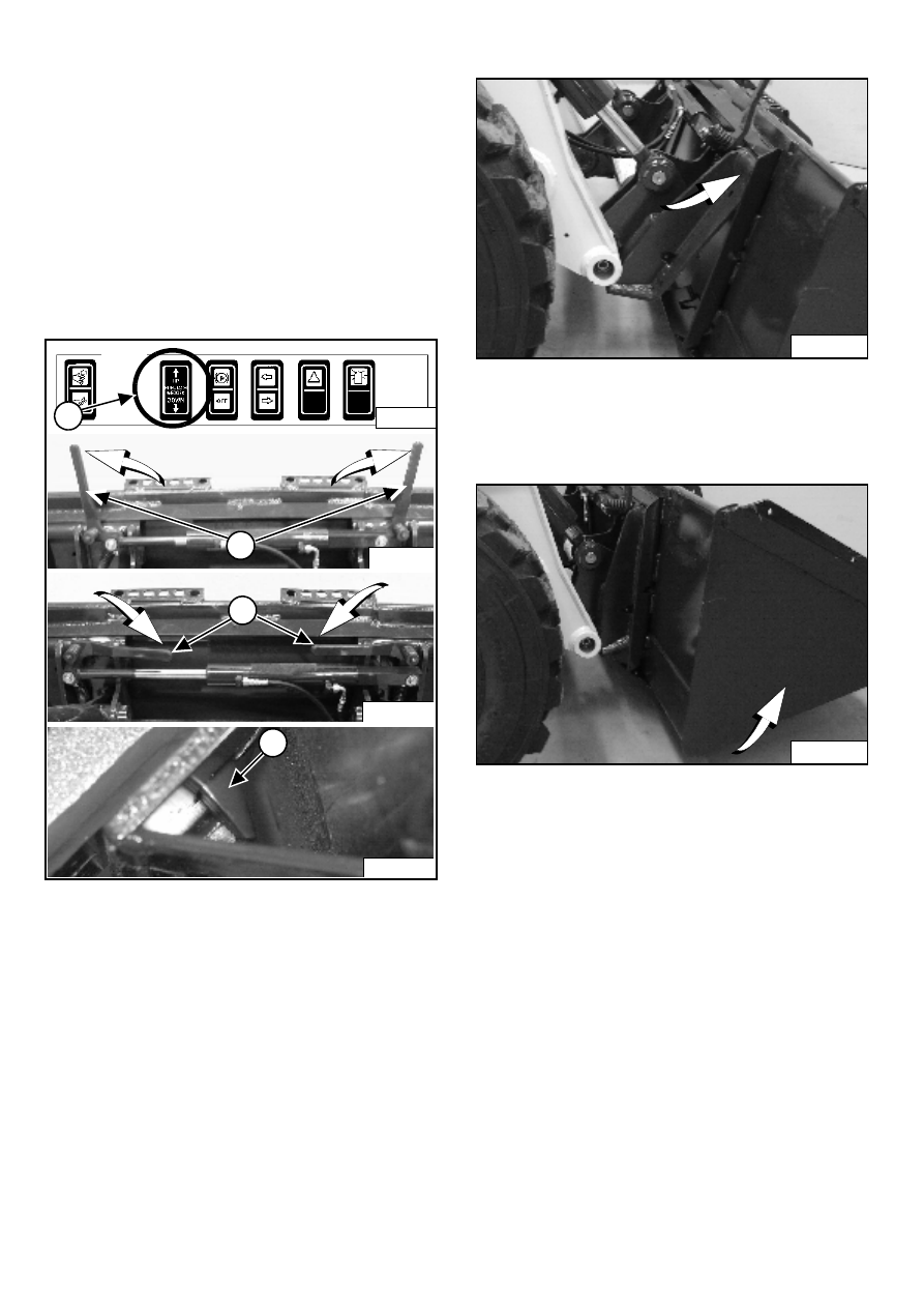
Push and hold BOB-TACH “WEDGES UP” switch (1)
[Figure 69] (Front Accessory Panel) until levers (2) are in
unlocked position (wedges fully raised).
NOTE: The Power Bob-Tach system has continuous
pressurized hydraulic oil to keep the wedges
in the engaged position and prevent
attachment disengagement. Because the
wedges can slowly lower, the operator may
need to reactivate the switch (WEDGES UP)
before installing an attachment to be sure
both wedges are fully raised before installing
the attachment.
Figure 70
Drive the loader forward until the top edge of the
Bob-Tach is completely under the top flange of the bucket
[Figure 70] (or other attachment).
Figure 71
Tilt the Bob-Tach backward until the cutting edge of the
bucket (or other attachment) is slightly off the ground
[Figure 71].
Push and hold BOB-TACH “WEDGES DOWN” switch
(Front Accessory Panel) (1) [Figure 69] until levers are
fully engaged (3) [Figure 69] in the locked position
(wedges fully engaged).
The wedges (4) [Figure 69] must extend through the
holes in the mounting frame of the bucket (or other
attachment), securely fastening the bucket to the
Bob-Tach.
P-31236
2
P-31235
3
P-31233
4
P-31233
B-15993
1
P-31231
P-31232
Нет комментариевНе стесняйтесь поделиться с нами вашим ценным мнением.
Текст