DAF 95XF. Manual — part 448
3
DIAGNOSIS
ZF Intarder
8-2
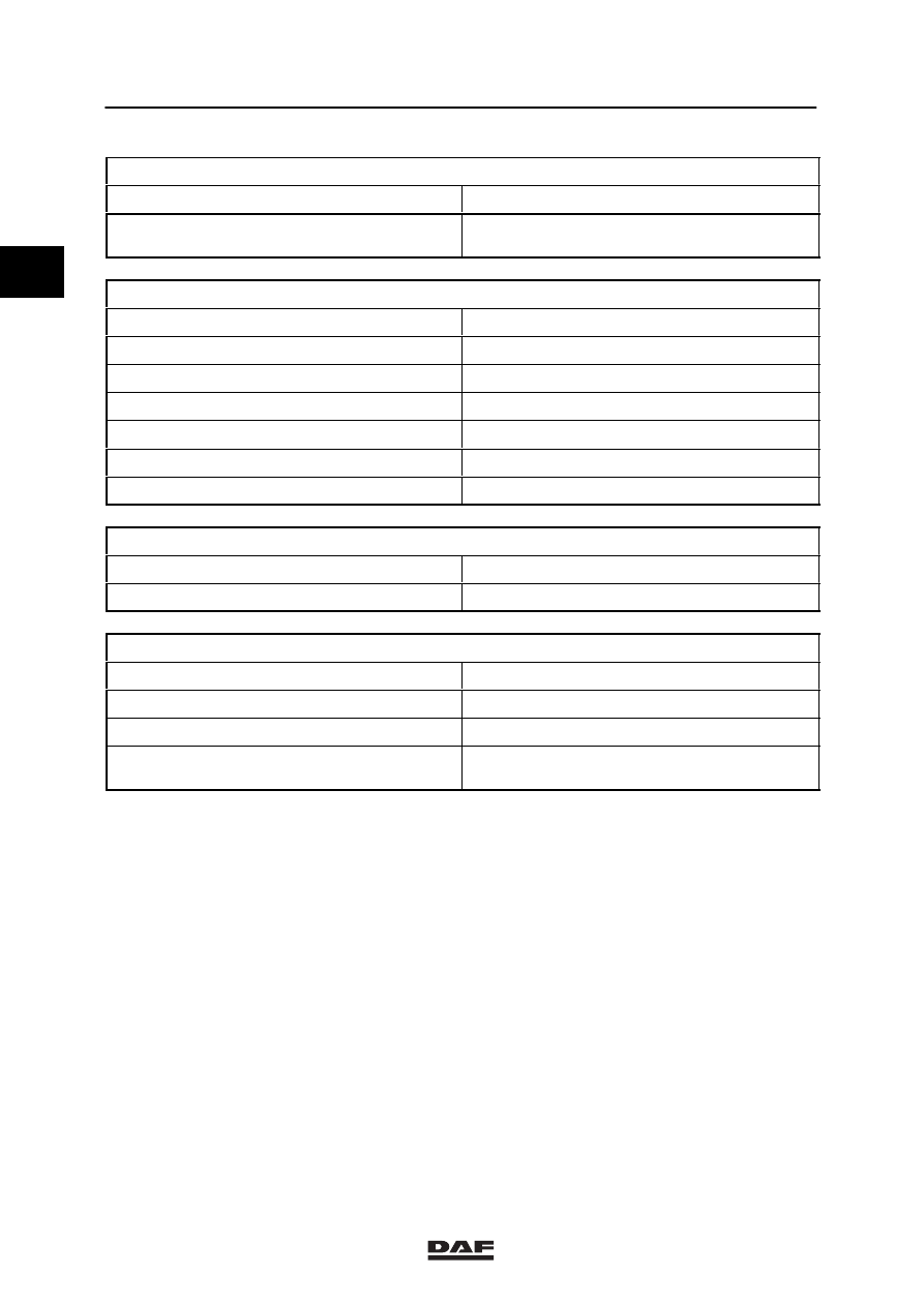
FAULT: DELAYED SWITCH-OFF
Possible cause
Remedy
Slow decrease of intarder pressure after
switch-off
Check system
FAULT: OIL LEAKAGE
Possible cause
Remedy
Oil level too high
Check oil level
Oil leak between gearbox housing and intarder
Replace gasket
Oil leak in pump
Replace O-ring
Oil leak in proportional valve
Replace O-ring
Oil leak in the accumulator
Replace O-ring
Oil leak in the drive flange
Replace O-ring
FAULT: AIR LEAKAGE
Possible cause
Remedy
Air leakage via air supply intarder valve
Replace O-ring
FAULT: COOLANT TEMPERATURE TOO HIGH
Possible cause
Remedy
Coolant level too high/low
Checking the coolant level
Temperature adjustment
Check system
Intarder pressure after intarder has been
switched off
Check system
1
ǹ 0002
3
Voith retarder
DIAGNOSIS
9-1
9. VOITH RETARDER
9.1 FAULT-FINDING TABLE
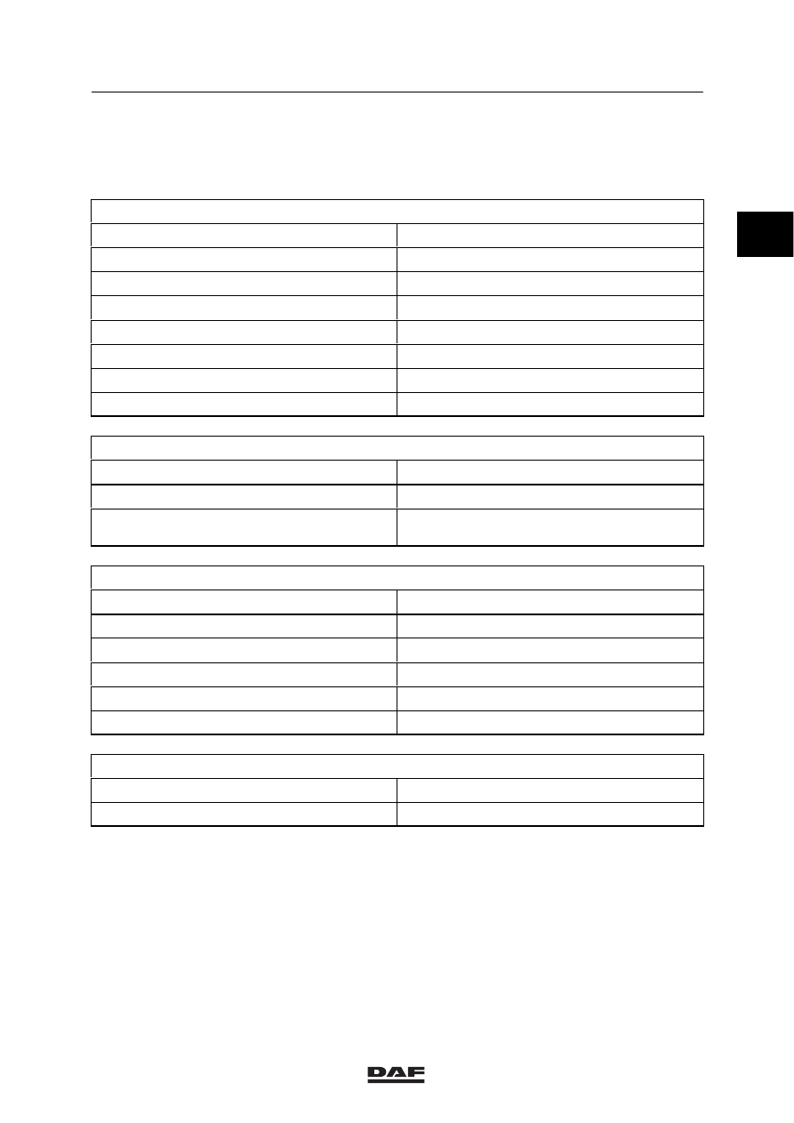
FAULT: NO/INSUFFICIENT BRAKE POWER
Possible cause
Remedy
Oil level too low
Check oil level
Intarder does not contain the specified oil
Change the oil
Reservoir pressure absent or too low
See “fault: air leakage”
No pneumatic service pressure
Check system
Pneumatic service pressure too low
Check system
No hydraulic service pressure
Check system
Hydraulic service pressure too low
Check system
FAULT: RETARDER REMAINS ENGAGED
Possible cause
Remedy
Oil level too high
Draining and filling
Service pressure is independent of the position
of the control lever
Check system
FAULT: DELAYED RESPONSE
Possible cause
Remedy
Air reservoir pressure absent or too low
See “fault: air leakage”
Slow build-up of pneumatic service pressure
Check system
Venting valve remains closed
Check system
Stator valves remain open
Check system
Shifting valve hangs
Check system
FAULT: DELAYED DECREASE OF BRAKE POWER
Possible cause
Remedy
No air escapes when retarder is switched off
Clean silencer
1
ǹ 0002
3
DIAGNOSIS
Voith retarder
9-2
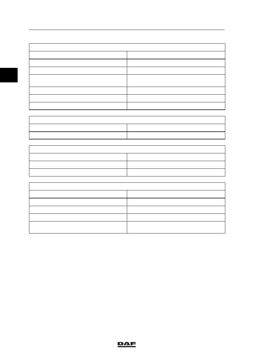
FAULT: OIL LEAKAGE
Possible cause
Remedy
Oil level too high
Draining and filling
Oil leak between adapter plate and retarder
Systeem controleren
Oil leak between gearbox housing and adapter
plate
Check system
Oil leakage at valve exhaust port
Check system
Oil leak in the drive flange
Replace O-ring
Butterfly valve defective
Check system
FAULT: AIR LEAKAGE
Possible cause
Remedy
Air leakage via proportional valve
Replace O-ring
FAULT: OIL LEAKAGE
Possible cause
Remedy
Oil leak in the drive flange
Replace O-ring
Butterfly valve defective
Check system
FAULT: COOLANT TEMPERATURE TOO HIGH
Possible cause
Remedy
Coolant level too low
Checking the coolant level
Oil level too high
Draining and filling
Temperature sensor or control unit defective
See system manual
Retarder service pressure after intarder has
been switched off
See system manual
1
ǹ 0002
3
Contents
HYDRAULIC GEARBOX CONTROL (HGS)
1
CONTENTS
Page
Date
1.
SAFETY INSTRUCTIONS
1-1
0002
. . . . . . . . . . . . . . . . . . . . . . . . . . . . . . . . . . . . . . . . . . . . . . .
. . . . . .
1.1
Safety instructions
1-1
0002
. . . . . . . . . . . . . . . . . . . . . . . . . . . . . . . . . . . . . . . . . . . . . . . .
. . . . . .
2.
GENERAL
2-1
0002
. . . . . . . . . . . . . . . . . . . . . . . . . . . . . . . . . . . . . . . . . . . . . . . . . . . . . . . . . . . .
. . . . . .
2.1
Description HGS system
2-1
0002
. . . . . . . . . . . . . . . . . . . . . . . . . . . . . . . . . . . . . . . . . . .
. . . . . .
3.
DESCRIPTION OF COMPONENTS
3-1
0002
. . . . . . . . . . . . . . . . . . . . . . . . . . . . . . . . . . . . . .
. . . . . .
3.1
Operation of gear lever unit
3-1
0002
. . . . . . . . . . . . . . . . . . . . . . . . . . . . . . . . . . . . . . . .
. . . . . .
3.2
Operation of gate selection and gear engaging cylinders
3-4
0002
. . . . . . . . . . . . . . .
. . . . . .
4.
INSPECTION AND ADJUSTMENT
4-1
0002
. . . . . . . . . . . . . . . . . . . . . . . . . . . . . . . . . . . . . . .
. . . . . .
4.1
Adjusting gear lever position
4-1
0002
. . . . . . . . . . . . . . . . . . . . . . . . . . . . . . . . . . . . . . . .
. . . . . .
4.2
Inspection, fluid level
4-3
0002
. . . . . . . . . . . . . . . . . . . . . . . . . . . . . . . . . . . . . . . . . . . . . .
. . . . . .
5.
REMOVAL AND INSTALLATION
5-1
0002
. . . . . . . . . . . . . . . . . . . . . . . . . . . . . . . . . . . . . . . .
. . . . . .
5.1
Removal and installation, entire gear lever unit
5-1
0002
. . . . . . . . . . . . . . . . . . . . . . . .
. . . . . .
5.2
Removal and installation, gear lever
5-2
0002
. . . . . . . . . . . . . . . . . . . . . . . . . . . . . . . . .
. . . . . .
5.3
Removal and installation, hydraulic lines
5-3
0002
. . . . . . . . . . . . . . . . . . . . . . . . . . . . .
. . . . . .
5.4
Removal and installation, gate selection and gear engaging cylinders
5-4
0002
. . . .
. . . . . .
6.
DRAINING AND FILLING
6-1
0002
. . . . . . . . . . . . . . . . . . . . . . . . . . . . . . . . . . . . . . . . . . . . . . .
. . . . . .
6.1
Draining, HGS system
6-1
0002
. . . . . . . . . . . . . . . . . . . . . . . . . . . . . . . . . . . . . . . . . . . . .
. . . . . .
6.2
Filling/bleeding, HGS system
6-2
0002
. . . . . . . . . . . . . . . . . . . . . . . . . . . . . . . . . . . . . . .
. . . . . .
ǹ 0002
2
Нет комментариевНе стесняйтесь поделиться с нами вашим ценным мнением.
Текст