DAF 95XF. Manual — part 533
EXPLANATORY NOTES ON THE MAINTENANCE ACTIVITIES
Inspection and adjustment
3-8
3.9 INSPECTION AND ADJUSTMENT, VALVE CLEARANCE AND UNIT
INJECTORS
VF engine
Note:
-
The valve clearances and unit injectors
must be adjusted when the engine is cold
(
≤ 60_C).
-
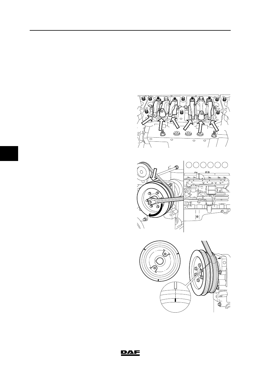
Each cylinder has three rockers:
1.
The rocker for the exhaust valves
2.
The rocker for the unit injector
3
.
The rocker for the inlet valves.
M2146
1
2
3
3
2
1
-
For the correct adjusting procedure for inlet
and exhaust valves and unit injectors, use
the marks made on the accessory drive
pulley (1) for the air-conditioning
compressor and water pump.
-
The direction of rotation of the crankshaft is
clockwise, as seen from the front of the
engine.
-
Cylinder 1 is on the timing-gear end, and
cylinder 6 on the flywheel end.
-
The injection sequence is 1-5-3-6-2-4.
-
Using the table below, and the marks on the
drive pulley and timing-gear cover, it is
possible to adjust the inlet and exhaust
valves and unit injectors of the cylinders
indicated.
Marks on drive pulley:
Adjustment of inlet and exhaust valves and
unit injectors of cylinder:
A
1 or 6
B
5 or 2
C
3 or 4
M2147
1
1 2 3 4 5 6
A
M2148
A
B
C
5
200424
Inspection and adjustment
EXPLANATORY NOTES ON THE MAINTENANCE ACTIVITIES
3-9
1.
Disconnect the battery earth lead.
2.
Remove the valve covers. See “Removal
and installation”.
3.
If the vehicle is equipped with a C-brake,
the C-brake must be removed first, see
chapter “Removal and installation”.
4.
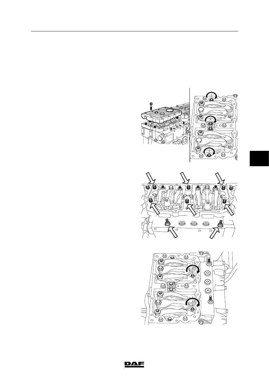
Tighten the rocker shaft attachment bolts to
the specified torque. See “Technical data”.
M2143
5.
Tighten the rocker-housing attachment
bolts, in the order shown in the diagram, to
the specified torque. See “Technical data”.
M2144
4
2
5
3
1
6
7
8
6.
Tighten the attachment bolts of the unit
injectors to the specified torque, see
“Technical data”.
M2145
5
200424
EXPLANATORY NOTES ON THE MAINTENANCE ACTIVITIES
Inspection and adjustment
3-10
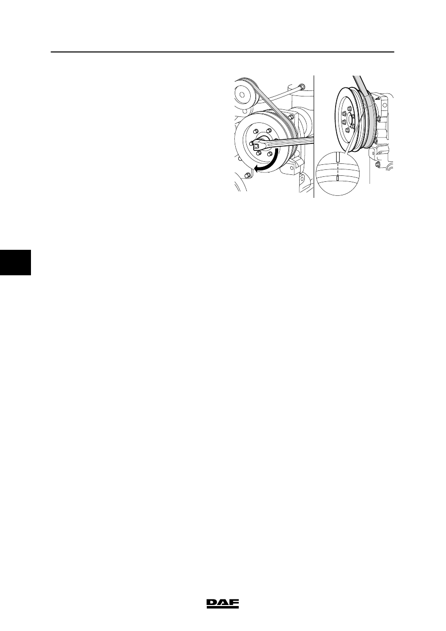
7.
Rotate the drive pulley (in the direction of
rotation of the crankshaft) using the
attachment nut on the pulley, until the “A”
marking is in line with the marking on the
timing cover.
8.
Check that the inlet and exhaust valves of
cylinder 1 are closed.
Note:
The valves are closed if both rockers can be
moved from side to side.
If necessary, rotate the drive pulley through
360
_ until the “A” marking is once again in
line with the marking on the cylinder block.
9.
Now adjust the valve clearance and the unit
injector of cylinder 1.
10. Repeat this adjustment procedure for the
remaining cylinders. Consult the following
table to this end.
Marks on drive pulley:
Adjustment of inlet and exhaust valves and
unit injectors of cylinder:
A
1 or 6
B
5 or 2
C
3 or 4
11. If required, fit the C-brake, see chapter
“Removal and Installation”.
12. Fit the valve covers. See “Removal and
installation”.
A
M2142
5
200424
Inspection and adjustment
EXPLANATORY NOTES ON THE MAINTENANCE ACTIVITIES
3-11
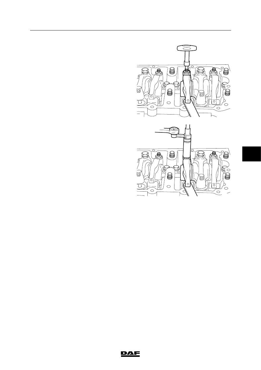
Adjusting the valve clearance
1.
Slacken the lock nut of the adjusting bolt.
2.
Using a feeler gauge and special tool (DAF
no. 1240043), adjust the specified valve
clearance, see “Technical data”.
3.
Tighten the adjusting bolt using special tool
(DAF no. 1240043) before removing the
feeler gauge.
The specified torque is 0.56 - 0.68 Nm.
M2140
4.
Hold the adjusting bolt in this position, and
tighten the lock nut using special tool (DAF
no. 1240042) to the specified tightening
torque, see “Technical data”.
M2141
5
200424
Нет комментариевНе стесняйтесь поделиться с нами вашим ценным мнением.
Текст