DAF 95XF. Manual — part 706
7
TECHNICAL DATA
Front axle(s), leading rear axle and steered trailing swivel axle
6-12
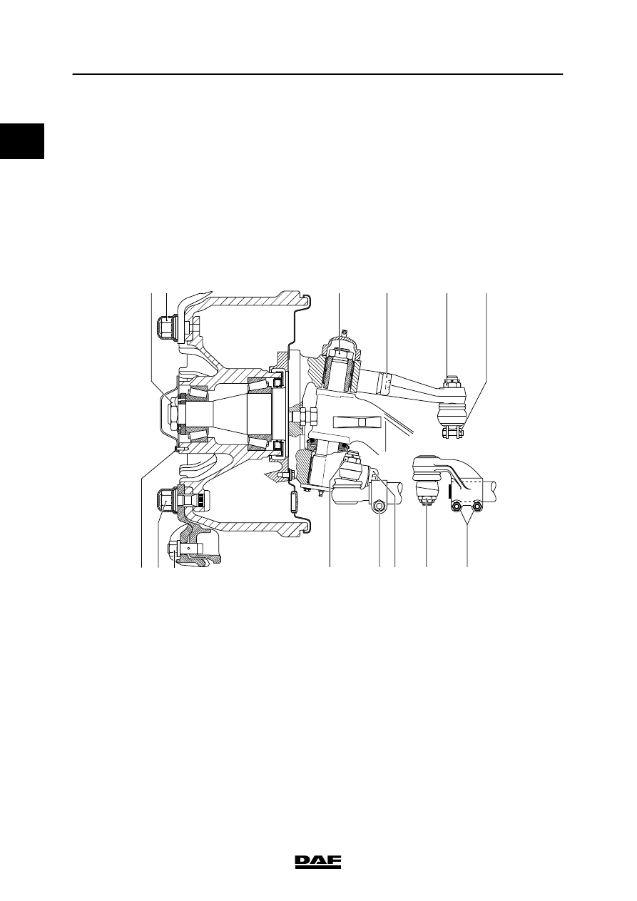
6.2 TIGHTENING TORQUES
The tightening torques stated in this section are
different from the standard tightening torques
included in the overview of standard tightening
torques. Any other threaded connections that
are not specified must therefore be tightened to
the tightening torque stated in the overview of
standard tightening torques.
When attachment bolts and nuts are to be
replaced, it is important that they are of exactly
the same length and property class as the ones
removed, unless stated otherwise.
A
H
G
K
I
F
B
L M
C
D
E
S7 00 844
N
O
A.
Wheel hub lock nut
210 Nm
B.
Wheel nut
700 Nm
(1)
C.
King-pin nut
-
if M27 (150N/152N)
595 Nm
(2)
-
if M33 (172N/182N/186N)
660 Nm
(2)
D.
Steering-rod arm attachment bolt
500 Nm + 90
_ angular displacement
(3)
E.
Steering-rod nut
-
if M20 castle nut
225 Nm
(4)
-
if M24 castle nut
285 Nm
(4)
-
if self-locking M20 nut
225 Nm
(5)
-
if self-locking M24 nut
285 Nm
(5)
0
200424

0
7
Front axle(s), leading rear axle and steered trailing swivel axle
TECHNICAL DATA
6-13
F.
Bolt, steering rod clamping bracket
-
if M10
47 Nm
(6)
-
if M12
80 Nm
(6)
G.
Wheel hub bolt
8.6 Nm
H.
Trilex mounting ring nut
700 Nm
(1)
I.
M20 nut (Trilex/Tublex wheel)
335 Nm
(1)
K.
Track-rod nut
-
if M20 castle nut
210 Nm
(4)
-
if M24 castle nut
260 Nm
(4)
-
if self-locking M20 nut
225 Nm
(5)
-
if self-locking M24 nut
285 Nm
(5)
L.
Bolt, track rod clamping bracket
-
if M12
80 Nm
(6)
-
if M14
170 Nm
(6)
M.
Track rod arm attachment bolt
500 Nm + 90
_ angular displacement
(3)
N.
Track-rod nut
-
if M20 castle nut
210 Nm
(4)
-
if M24 castle nut
260 Nm
(4)
-
if self-locking M20 nut
225 Nm
(5)
-
if self-locking M24 nut
285 Nm
(5)
O.
Bolt, track rod clamping bracket
-
if M12
80 Nm
(6)
-
if M14
170 Nm
(6)
Remarks
(1)
Retighten after 100 km; if new wheel studs have been
fitted, the wheels need additional retightening after
500 km.
(2)
Apply Loctite 243 to the nut.
(3)
Fit new attachment bolts. Apply Loctite 243 to the
attachment bolts.
(4)
Tighten until the split pin fits (max. 60
°). It is not
allowed to fit a self-locking nut instead of a castle nut.
(5)
Check the thread of the ball end for damage before
fitting a new self-locking nut to the ball end. Screw a
new non-self locking nut onto the ball end by hand to
check it. If the new non-self locking nut cannot be
screwed down over the whole thread by hand, the ball
end must be replaced. Fit new self-locking nut. Apply
Loctite 243 to the nut.
(6)
Fit new self-locking nut.
If a new self-locking nut is fitted to a
ball end with a damaged thread, this
can give rise to dangerous
situations.
200424
7
TECHNICAL DATA
Front axle(s), leading rear axle and steered trailing swivel axle
6-14
A
B
C
B
A
D
B
C
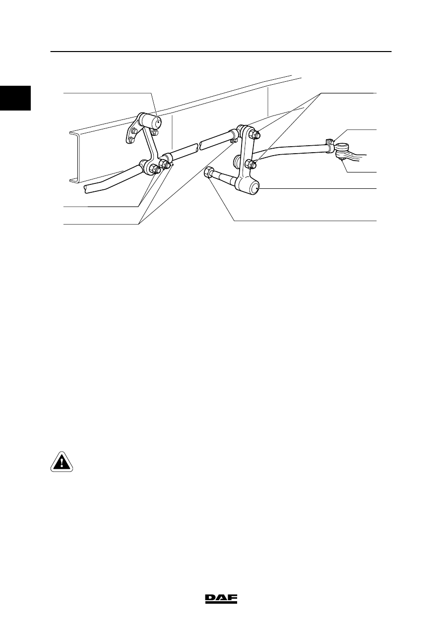
S7 00 154
A.
Idler-arm lock nut
185 Nm
B.
Steering-rod attachment nut
-
if M20 castle nut
225 Nm
(1)
-
if M24 castle nut
285 Nm
(1)
-
if self-locking M20 nut
225 Nm
(2)
-
if self-locking M24 nut
285 Nm
(2)
C.
Bolt, steering rod clamping bracket
-
if M10
47 Nm
(3)
-
if M12
80 Nm
(3)
D.
Idler-arm attachment nut
750 Nm
Remarks
(1)
Tighten until the split pin fits (max. 60
°).
It is not allowed to fit a self-locking nut
instead of a castle nut.
(2)
Check the thread of the ball end for damage before
fitting a new self-locking nut to the ball end. Screw a
new non-self locking nut onto the ball end by hand to
check it. If the new non-self locking nut cannot be
screwed down over the whole thread by hand, the ball
end must be replaced. Fit new self-locking nut. Apply
Loctite 243 to the nut.
(3)
Fit new self-locking nut.
If a new self-locking nut is fitted to a
ball end with a damaged thread, this
can give rise to dangerous
situations.
0
200424

;) VHULHV
&RQWHQWV
',$*126,6
&217(176
3DJH
'DWH
67((5,1* 0(&+$1,60 *(1(5$/
)DXOWILQGLQJ WDEOH
Нет комментариевНе стесняйтесь поделиться с нами вашим ценным мнением.
Текст