DAF 95XF. Manual — part 616
8
HYDRAULIC LIFTING GEAR
Disassembly and assembly
5-6
5.3 DISASSEMBLY AND ASSEMBLY, CYLINDER
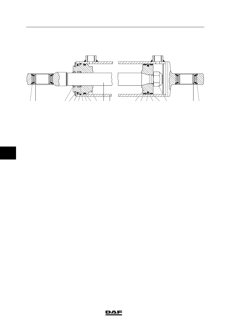
1 2
1
2
11 12
13 14 15 16 17 18
3 4 5 6
8 9
A
B
10
7
A8 00 248
Disassembly of the cylinder
1.
Remove the cylinder from the vehicle, see
the chapter “Removal and installation”.
2.
Check whether all the oil has been drained
from the cylinder.
3.
Clean the cylinder before disassembly.
Work in very clean conditions. Make sure
that the piston rod is not damaged during
the repair or maintenance activities.
4.
Remove the circlips (1) and push the
bearing (2) from the eye.
5.
Remove the circlip (4).
6.
Remove the dirt which has collected before
the O ring (5) and remove the O ring (5).
7.
Use a plastic mallet to tap the piston-rod
guide (10) deeper into the cylinder, until the
spring clip (6) can be removed. Make sure
that the piston rod is not damaged in the
process.
8.
Remove the spring clip (6) from the cylinder.
9.
Pull the entire length of the piston rod (11)
out of the cylinder. The piston-rod guide
(10) will come out of the cylinder together
with the piston rod.
10. Remove the plastic rings (14) and (16) from
the piston.
6
ǹ 0001
8
Disassembly and assembly
HYDRAULIC LIFTING GEAR
5-7
11. Remove the nut (18) and use a plastic
mallet to tap the piston (13) from the piston
rod.
12. Slide the piston-rod guide (10), the O ring
(5) and the circlip (4) from the piston rod.
Pay attention to the position of the circlip.
13. Remove the dirt scraper (3), sealing ring
(7), O ring (9) and plastic ring (8) from the
piston rod guide.
14. Remove the sealing ring (15) and the O ring
(16) below from the piston.
Assembly of the cylinder
1.
Check the sealing-ring chambers and
recesses, the dirt scraper and O rings for
impurities.
Check the surfaces of the piston rod and
the cylinder casing for signs of wear and/or
damage. Even the slightest damage can
cause a leak.
Check the condition of the spring clip (6)
and the circlip (4). Replace these, if
necessary.
Replace the sealing rings, dirt scraper and
O rings.
Apply a layer of grease to the O rings and
running surfaces of the sealing rings and
dirt scraper prior to assembly.
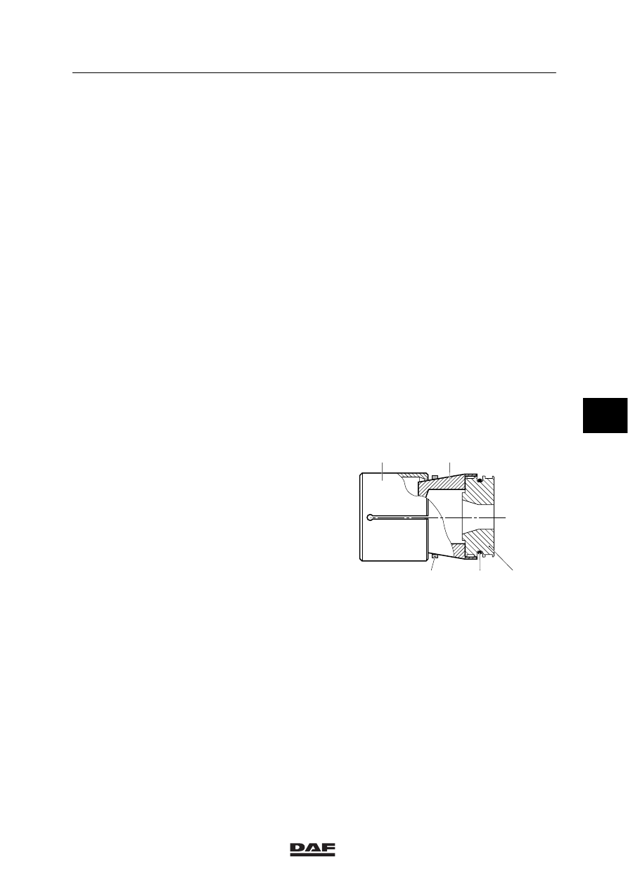
2.
Install the O ring (16) to the piston (13).
3.
Heat the new sealing ring (15) for 5 minutes
in water at a temperature of 90
_C.
4.
Fit the special tool (DAF no. 1310472), see
“b” in the illustration, on the piston (13).
5.
Slide the heated sealing ring (15) onto the
piston using special tool
(DAF no. 1310473), see “a” in the
illustration.
13
15
16
b
a
A8 00 260
6
ǹ 0001

8
HYDRAULIC LIFTING GEAR
Disassembly and assembly
5-8
6.
Fit the special tool (DAF no. 1310474), see
“c” in the illustration, over the sealing ring
(15) and leave the special tool on the
sealing ring for 5 minutes.
7.
Install the sealing ring (7) with the recess
aimed towards the piston (13) into the
piston-rod guide (10). To do so, press the
sealing ring together as shown in the
illustration. Make sure that no sharp corners
are formed.
Subsequently, press the sealing ring into
the chamber of the piston-rod guide as
shown in the illustration.
8.
Install the dirt scraper (3) into the piston-rod
guide (10).
You should proceed in the same manner as
when installing the sealing ring (7).
9.
Install the plastic ring (8) onto the piston-rod
guide (10).
You should proceed in the same manner as
when installing the sealing ring (15) on the
piston.
10. Install the O ring (9) onto the piston-rod
guide (10). The O ring should fall into the
groove at the piston side. The plastic ring
(8) is positioned on the circlip side.
11. Slide the circlip (4) into the correct clamping
position over the piston rod.
12. Slide the O ring (5) over the piston rod.
13. Oil the piston rod (11) and slide the
piston-rod guide (10) onto the piston rod.
13
15
16
c
A8 00 261
A8 00 262
A8 00 263
6
ǹ 0001
8
Disassembly and assembly
HYDRAULIC LIFTING GEAR
5-9
14. Install the piston (13) on the piston rod,
replace the self-locking nut (18) and tighten
the nut to the prescribed tightening torque,
see main group “Technical data”.
15. Apply some oil to the cylinder casing.
16. Install the plastic rings (14) and (17) on the
piston. The gap openings of the rings
should be opposite each other. During the
installation of the piston in the cylinder, the
gap openings may not be positioned near
line connection A of the cylinder.
17. Apply some oil to the plastic rings (14) and
(17) and the sealing ring (15) and slide the
piston into the cylinder. When sliding the
piston into the cylinder, the plastic rings
should be pressed into the grooves.
18. Slide the piston-rod guide (10) into the
cylinder and tap the piston-rod guide
carefully into the cylinder using a plastic
mallet until the spring clip (6) can be fitted.
Make sure that the piston rod is not
damaged in the process.
19. Fit the spring clip (6) into the cylinder. Make
sure that the entire circlip is positioned
correctly in the groove.
20. Pull back the piston-rod guide (10) using the
piston rod, until the piston-rod guide is in
contact with the spring clip (6).
21. Fit the O ring (5).
22. Install the circlip (4). Make sure that the
entire circlip is positioned correctly in the
groove.
23. Install one of the circlips (1) and press a
new bearing (2) into the eye.
24. Install the second circlip (1).
25. Check the cylinder for internal and external
leakage, see chapter “Inspection and
adjusting”.
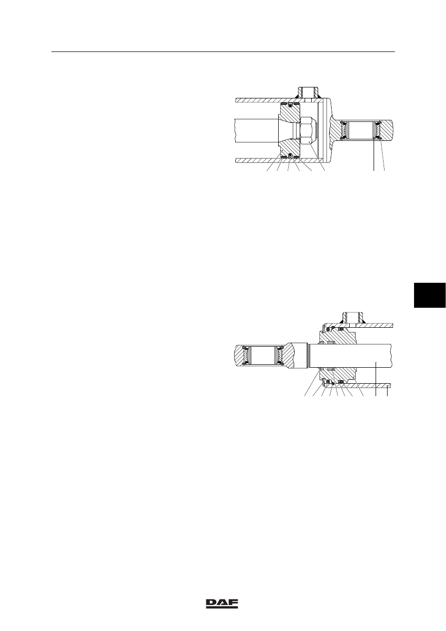
1
2
13 14 15 16 17 18
B
A8 00 286
11 12
3 4 5 6
8 9
A
10
7
A8 00 285
6
ǹ 0001
Нет комментариевНе стесняйтесь поделиться с нами вашим ценным мнением.
Текст