DAF 95XF. Manual — part 122
6
Description of components
DESCRIPTION OF BRAKE COMPONENTS
1-25
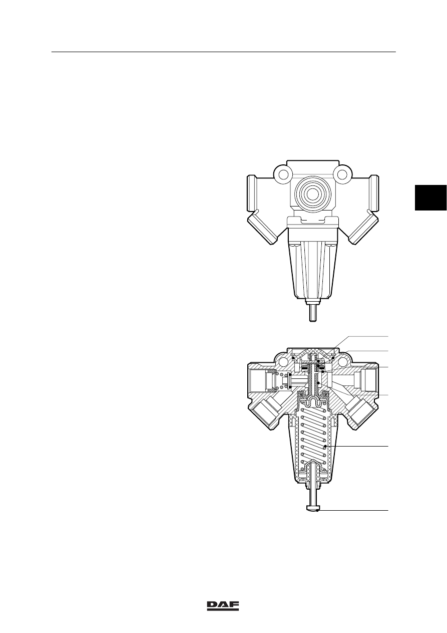
1.13 PRESSURE-RELIEF VALVE WITH NON-RETURN VALVE
Purpose
The purpose of the pressure-limiting valve with
non-return valve is to limit the output pressure to
a specified preset value (8 bar).
Lower pressures are passed unreduced. This
valve also includes a non-return valve for
circuit 3 of the brake system.
Operation
Compressed air is input at connection
number 12 (maximum system pressure).
The storage reservoir for circuit 3 is filled via
port 11.
At port numbers 21, 22 and 23, the
pressure-limited air is once again bled. If the
exhaust air has not yet reached the limit value,
piston-shaped valve (2) is open.
When the pressure at the piston-shaped
valve (2) reaches the limit set by the adjusting
screw (6), valve (2) will be forced downwards
against the pressure of spring (5), until it
contacts seat (3).
No air can now pass.
If pressure at ports (21), (22) and (23) exceeds
that at ports 11 and 12, via an opening in
piston (4), the pressure will raise spring-loaded
seal (1), from piston-shaped valve (2). As a
result the air can flow back to ports (11) and
(12).
R600226
11
2
3
6
5
12
23
21
22
1
4
3
ǹ 0006
6
DESCRIPTION OF BRAKE COMPONENTS
Description of components
1-26
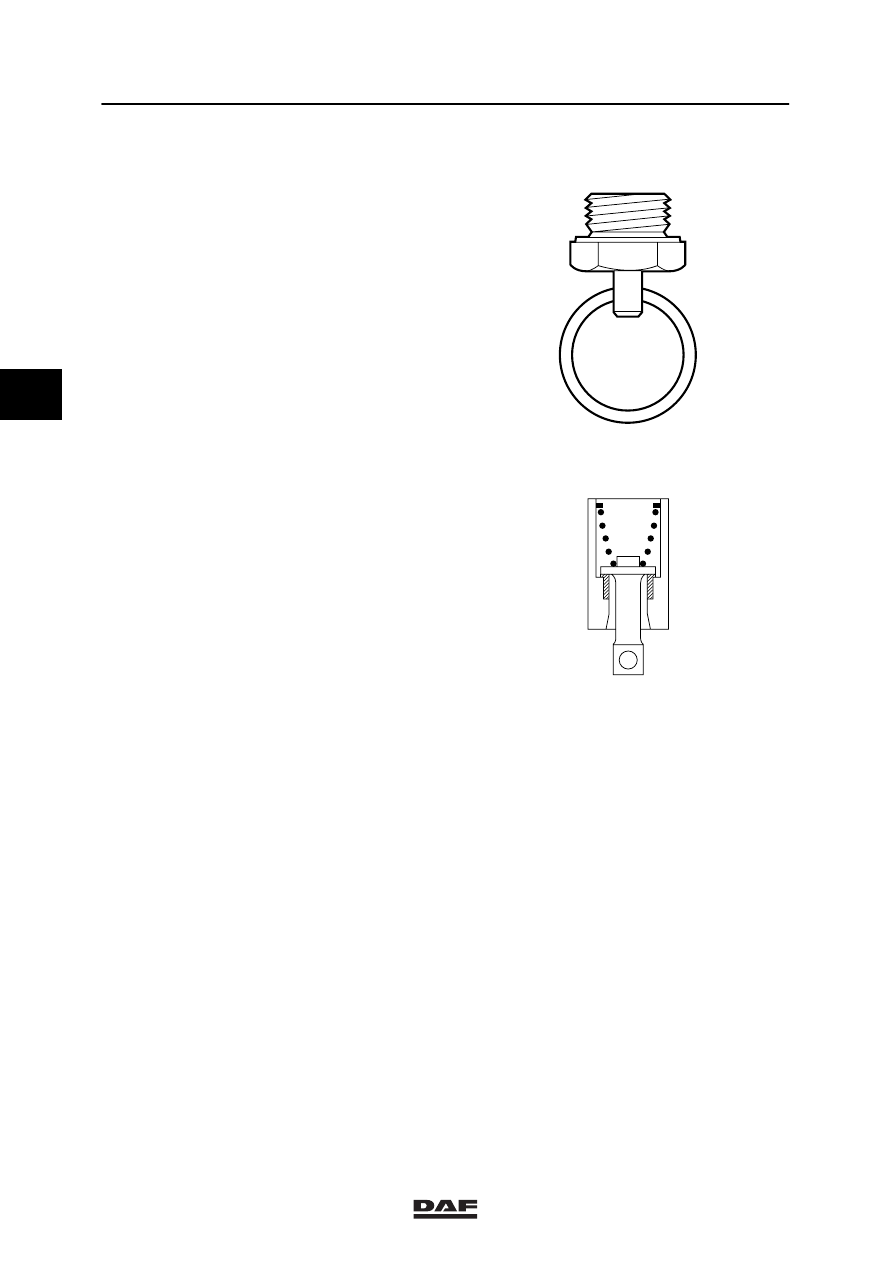
1.14 WATER BLOW-OFF VALVE
Purpose
The purpose of the water blow-off valve is to
enable any condensate in the air reservoir or air
lines to be drained and, if necessary, to vent the
system.
Operation
The valve is kept closed by the spring and the
reservoir pressure. By pushing the pin
sideways, the valve is lifted off the seat, allowing
condensate and compressed air to escape.
When the pin is released, the valve is closed.
Check that no other components are present
under the blow-off plug, as these could be
fouled during the blow-off process.
R600046
3
ǹ 0006
6
Description of components
DESCRIPTION OF BRAKE COMPONENTS
1-27
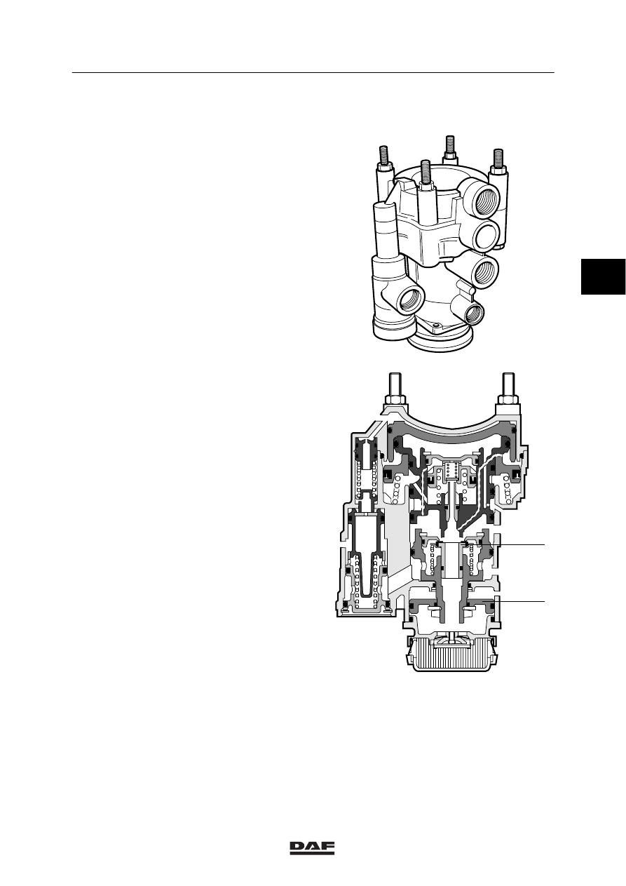
1.15 (SEMI-)TRAILER-REACTION VALVE
WABCO design
Purpose
The purpose of the trailer-reaction valve is to
pass on the brake commands from the tractor to
the (semi-)trailer.
Operation
Driving
Port (11) is connected with a reservoir, and
port (43) with the parking-brake valve. Both are
pressurised and in a state of balance. The
service -coupling head is connected via port (22)
and exhaust valve (2), and vent (3), to the
atmosphere.
R600157
R600122
2
1
42
22
12
43
3
11
41
3
ǹ 0006
6
DESCRIPTION OF BRAKE COMPONENTS
Description of components
1-28
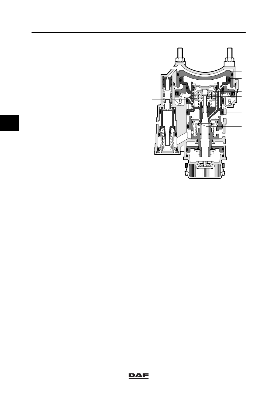
Braking with the service brake
Pressure build-up
With the service-brake valve, circuit 1, port (41),
and circuit 2, port (42), are pressurised.
This will force pistons (4) and (5) downwards,
closing exhaust valve (2) and opening inlet valve
(3). The reservoir pressure at port (11) can now
flow via inlet valve (3) to port (22), (yellow)
(semi-)trailer service-coupling head, and will
cause the (semi-)trailer to brake.
Regulating
When a preset value has been reached in the
output pressure at port (22), this pressure will
once again force pistons (4) and (5) upwards,
thus closing inlet valve (3).
There is now a state of balance between the
input pressure at port (41), and output pressure
at port (22).
Releasing
When the service-brake valve is released, the
input pressure at ports (41) and (42) falls away.
Pistons (4) and (5) are forced upwards, by the
output pressure at port 22.
As a result, inlet valve (3) is closed, and exhaust
valve (2) opened, thus linking port (22) with the
exhaust.
R600123
3
9
5b
5a
2
4
5
6
7
42
22
12
43
11
41
3
ǹ 0006
Нет комментариевНе стесняйтесь поделиться с нами вашим ценным мнением.
Текст