DAF 95XF. Manual — part 368
5
CHANGES IN THE ELECTRICAL SYSTEM
Changes in the electrical system from chassis number 0E527418
5-24
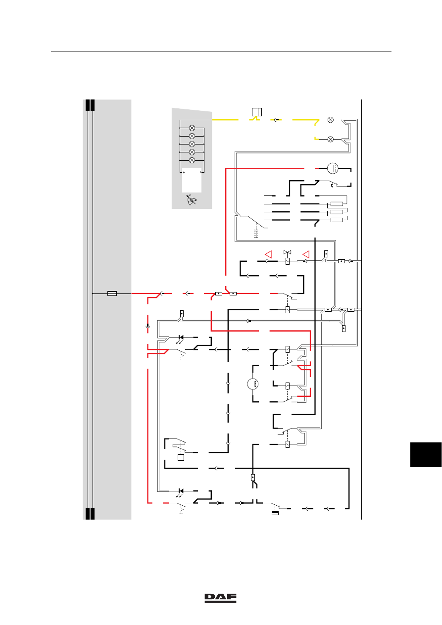
BRIEF DESCRIPTION OF THE
RECIRCULATION VALVE
If switch C802 (air-conditioning recirculation
valve) is activated, a voltage is applied to point 1
of relays G257 and G258. As a result, pin 2 of
recirculation-valve motor B252 is connected to
earth and simultaneously pin 1 of B252 is
connected to the positive voltage. This will
activate motor B252 and close the recirculation
valve.
If C802 is not activated, no voltage is applied to
relays G257 and G258. As a result, the direction
of flow of the current through motor B252 is
reversed and the recirculation valve will open.
BRIEF DESCRIPTION OF THE
AIR-CONDITIONING SYSTEM
When the air-conditioning system is engaged
with switch C760, a voltage is applied to both
relay G279 and G267 through wire 4655, switch
E508 (air-conditioning compressor temperature
switch), E509 (air-conditioning high/low pressure
operating switch) and wire 4657.
As a result, the heater fan (B015) will start
operating in position 1 and the air-conditioning is
activated.
SEE THE SYSTEM MANUAL FOR MORE
INFORMATION
11
ǹ 0209
5
Changes in the electrical system from chassis number 0E527418
CHANGES IN THE ELECTRICAL SYSTEM
5-25
20
1316630/30
EL000627
1
23456789
1
0
1
1
1
2
1
3
1
4
1
5
1
6
1
7
1
8
1
9
2
0
2
1
2
2
2
3
2
4
2
5
2
6
2
7
2
8
2
9
3
0
3
1
3
2
3
3
3
4
3
5
3
6
3
7
3
8
3
9
4
0
4
1
4
2
4
3
4
4
4
5
4
6
4
7
4
8
4
9
5
0
5
1
5
2
5
3
4655
4655
4655
4655
1201
1201
2622
16/202
2622
2622
4650
4650
4651
4652
4654
4654
4658
4654
4650
4659
2622
1201
1201
1201
4659
4659
4659
1201
4656
4656
4656
4656
4657
1201
4659
5054
5053
4657
1201
4657
1201
4655
1201
5055
5055
5055
1201
4656
4656
4657
4657
4655
1201
1201
D852
D878
1010
1000
1010
1000
E031
15A
3
397
B501
2
2
2
397
C053
1
2
C052
1
2
C882
1
4
5
3
2
6
5
3
2
14
B015
M
8
7
E508
3
1
E509
1
2
P
1
397
DVB
9
397
1
376
4
397
2
175
16
376
15/401
G279
5
1
2
4
3
2
1
B043
G267
3
1
24
5
B252
M
1
2
3
54
G257
1
2
3
54
G258
1
2
12
397
14
114
8
397
D
114
1
183
!
!
21
376
5
397
3
175
2
183
C760
3
2
1
5
C802
3
2
1
5
17
376
11
ǹ 0209
5
CHANGES IN THE ELECTRICAL SYSTEM
Changes in the electrical system from chassis number 0E527418
5-26
35 CONVERTER/RADIO
The following description of the operation
and connection is intended as a general
guideline only.
Also refer to the manufacturer’s installation
instructions supplied with the radio.
For more information, also see block 6,
“Connecting the radio”.
The radio has an aerial connection and two
loudspeaker outputs, to which the speakers
B024 and B025 can be connected. Two filters for
the loudspeakers can also be connected to the
radio. To each of these filters (B186 and B187)
two loudspeakers can be connected (B178,
B179 and B180 and B181).
The 12-V output (pin A4) of the converter (D895)
can also be connected to a transmitter (B026) to
provide it with a supply voltage.
VARIANTS
Location
22
Connector 190: only for XC. For XH and
XL this is connector 291.
38
Wire no.: 2630. This wire should be
connected to one of the search lighting
switch wires.
41
Wire no.: 1108. This wire should be
connected to wire 1108 coming from the
24/12V converter.
11
ǹ 0209

5
Changes in the electrical system from chassis number 0E527418
CHANGES IN THE ELECTRICAL SYSTEM
5-27
35
1316630/30
EL000628
1
23456789
1
0
1
1
1
2
1
3
1
4
1
5
1
6
1
7
1
8
1
9
2
0
2
1
2
2
2
3
2
4
2
5
2
6
2
7
2
8
2
9
3
0
3
1
3
2
3
3
3
4
3
5
3
6
3
7
3
8
3
9
4
0
4
1
4
2
4
3
4
4
4
5
4
6
4
7
4
8
4
9
5
0
5
1
5
2
5
3
1100
1130
1130
1100
1100
1106
1108
1108
4001
4002
1147
1147
1108
1107
1353
1106
1108
1108
1108
1353
4827
4827
4828
4828
4831
4831
4832
4832
4829
4830
4833
4834
4829
4830
4833
4834
4829
4830
4833
4834
1107
1108
2630
4540
4540
4542
4542
4541
4541
4543
4543
15/402
19/402
20/402
3/402
10/403
1/402
1/412
2/412
4/412
6/412
12/403
B178
B179
1
194
2
194
5
194
6
194
B180
B181
G015
85
1
B010
50
1
3
194
4
194
7
194
8
194
17
190
18
190
19
190
20
190
3/427
1/427
B1
A2
B2
3
189
7
190
3
190
12
194
15/403
C539
L2
B186
L2
L1
L1
R2
B187
R2
R1
R1
A4
24V
24V
D895
12V
12V
B026
12V
2
1
7/424
4/424
D878
E037
15A
30
86
85
87A
87
G178
1100
1147
1130
E027
10A
1010
1000
1010
1000
E028
15A
!
!
!
G231
30
85
86
87A
8
7
!
8/424
12
185
B024
13
185
7
187
B025
8
187
12V
1
2V
B185
12V
LL
R
R
11
ǹ 0209
Нет комментариевНе стесняйтесь поделиться с нами вашим ценным мнением.
Текст