DAF 95XF. Manual — part 497
3
ZF INTARDER
General
2-2
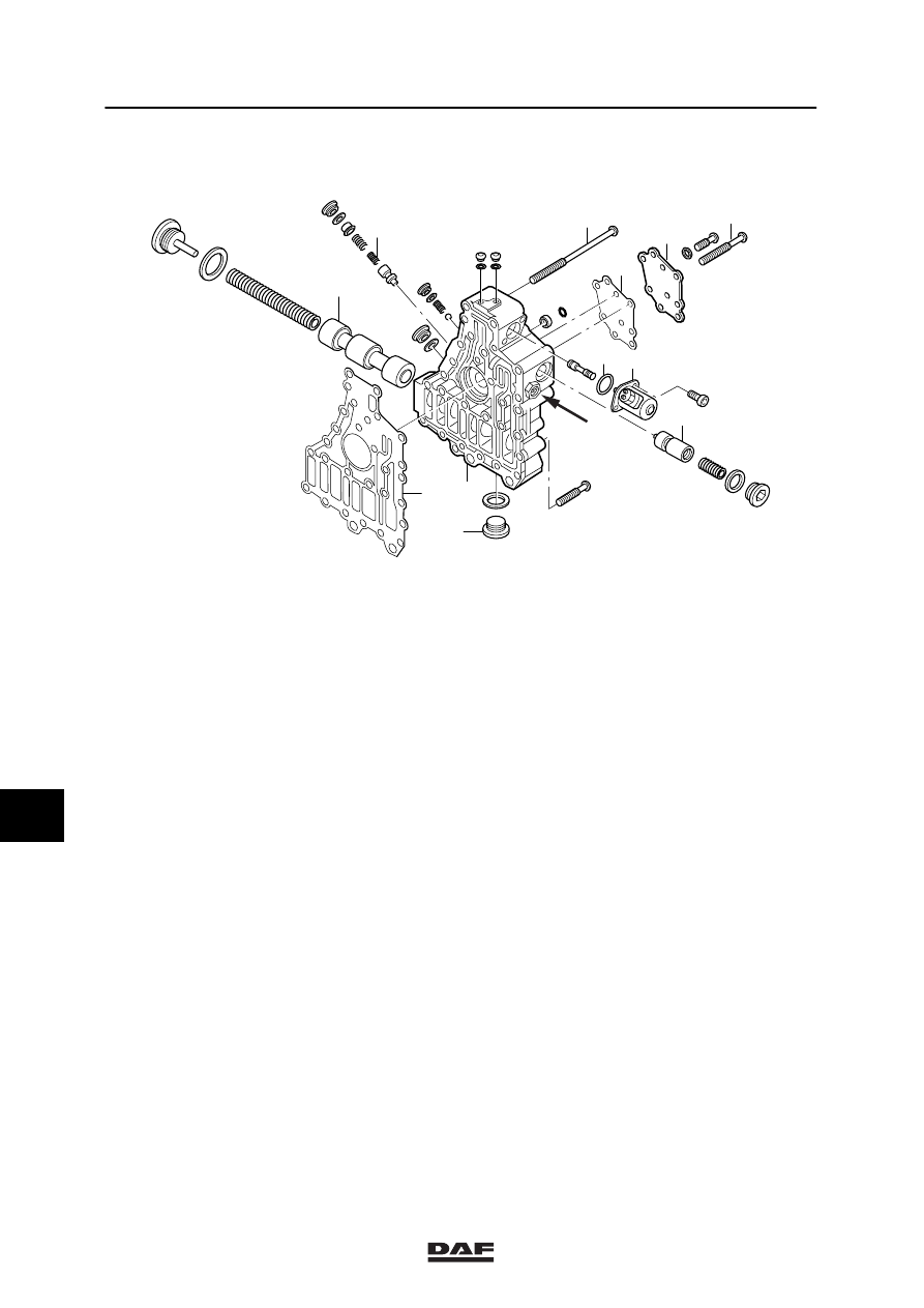
2.2 OVERVIEW DRAWING OF HYDRAULIC CONTROL UNIT
V300075
5
8
7
6
5
4
2
3
1
9
10
5
1.
Fixing bolt
2.
Fixing plate
3.
Gasket
4.
Fixing bolt
5.
Plungers and springs
6.
Drain plug
7.
Control unit housing
8.
Gasket
9.
Proportional valve
10. O-ring
9
ǹ 0002
3
General
ZF INTARDER
2-3
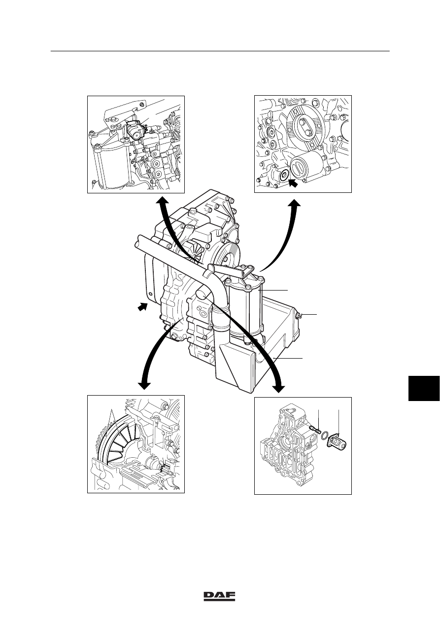
2.3 LOCATION OF MAIN COMPONENTS
3
7
2
9
4
10
8
1
5
6
V300236
1.
Control plunger of the proportional intarder
valve
2.
Sealing plug for the spring of the
change-over valve
3.
Accumulator
4.
Heat exchanger
5.
Drive sprockets
6.
Stator and rotor
7.
Air supply magnetic valve
8.
Proportional valve
9.
Connection to gearbox
10. Coolant temperature sensor
9
ǹ 0002
3
ZF INTARDER
General
2-4
9
ǹ 0002
3
Inspection and adjustment
ZF INTARDER
3-1
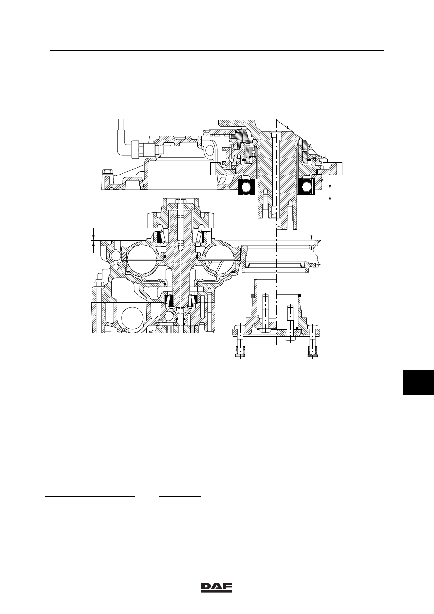
3. INSPECTION AND ADJUSTMENT
3.1 INSPECTING AND ADJUSTING THE AXIAL CLEARANCE OF THE OUTPUT
SHAFT BEARING
A
C
A
B
D
V300070
4.
Measure and note down distance “A - B”
from sealing surface (A) with gasket to
contact surface (B).
5.
Measure and note down distance “D” from
the outer ring of the ball bearing to the
gasket on the gearbox.
Example:
Distance A - B
=
10.5 mm
Distance D
=
10.0 mm
Difference
=
0.5 mm
Maximum clearance
0.1 mm
Required thickness of
filler ring
0.4 mm
9
ǹ 0002
Нет комментариевНе стесняйтесь поделиться с нами вашим ценным мнением.
Текст