DAF 95XF. Manual — part 539
EXPLANATORY NOTES ON THE MAINTENANCE ACTIVITIES
Inspection and adjustment
3-32
3.24 CHECKING THE AUTOMATIC BRAKE ADJUSTER
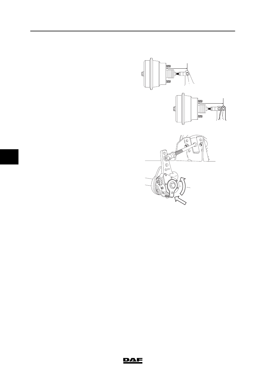
Checking the brake adjuster travel
1.
Measure the basic setting L1.
2.
Measure the position when the brakes are
applied, L2 (minimum brake system
pressure 6 bar).
3.
Calculate the brake adjuster travel L3 (L3 =
L2 – L1). Compare the calculated value to
the specified value, see “Technical data”.
4.
If the brake adjuster travel differs
considerably from the specified value, take
the following action:
-
Check whether the control plate (1) is
locked in respect of the fixed bracket.
If not, turn the control plate as far as
possible (until the internal stop is felt) in
the direction in which the brake
adjuster is moved during braking.
Fix the control plate in this position, via
the attachment nut on the fixed bracket.
-
Check the internal slip using a torque
wrench.
Checking the internal slip
1.
Make certain that there is sufficient
pressure in the reservoirs (min. 6.5 bar).
2.
Release the parking brake.
3.
Fit a torque wrench and turn the set
hexagon anticlockwise.
4.
If a tightening torque of 18 Nm is not
reached, but the worm shaft turns at a
lower torque, the brake adjuster should be
replaced.
M6101
L2
L1
M6005
1
5
200424
Inspection and adjustment
EXPLANATORY NOTES ON THE MAINTENANCE ACTIVITIES
3-33
3.25 INSPECTION AND ADJUSTMENT, LOAD-DEPENDENT CONTROL VALVE,
LEAF SUSPENSION
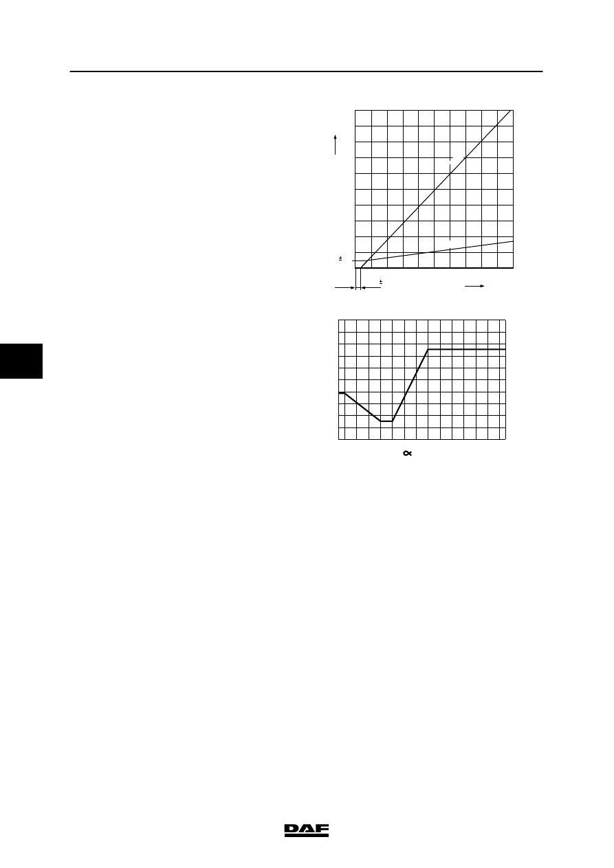
Explanatory notes on instruction plate
The instruction plate contains details of the axle
loads and output pressures; these correspond to
the order of the axles underneath the vehicle.
So “1” is the front axle, etc.
To check the load-dependent control valve, the
details on the instruction plate relating to the
“driven axle” are therefore vital.
1.
Measure the rear axle load.
Note:
Vehicles equipped with a trailing axle with
leaf spring should be adjusted with the
trailing axle lowered. When adjusting the
ALR valve, take the weight of both axles.
2.
Check the attachment of the control lever
and its ease of operation.
3.
Also check whether the correct valve and
the correct springs have been fitted (for
information, see the instruction plate).
4.
Check length L of the control lever (see
instruction plate).
5.
Connect pressure gauge (1) to the test
connection (1) of the load-dependent valve
and pressure gauge (2) to the test
connection on one of the spring-brake
cylinders (service-brake connection) of the
rear axle.
6.
Make sure that the reservoir pressure
exceeds 6.5 bar.
M6045
MEEREGELVENTIEL
EMPTY-LOAD VALVE
LAST-LEER VENTIEL
VALVE CHARGE-VIDE
VALVOLA VUOTO-CARICO
VALVULA VIDA-CARGA
ASLAST
AXLE LOAD
ACHSLAST
CHARGE SOUS ESSIEU
CARICO ASSE
CARGA EJE
UITGESTUURDE DRUK
DELIVERY PRESSURE
AUSGESTEUERTER DRUCK
PRESSION DELIVREE
PRESSIONE USCITA
PRESION DE SALIDA
G
p
2
B
ALGDRUK
PRESSURE BELLOWS
BALG DRUCK
PRESSION COUSSIN
PRESS.CUSCINI ARIA
PRESION FUELLES
p3
bar
bar
x 10
4
N
AUTOM. LASTAFHANKELIJKE REMKRACHTREGELING
AUTOM. LOAD SENSING DEVICE
AUTOM LASTABHANGIGE BREMSKRAFT REGELINR.
DISPOSITIF DE CORRECTION AUTOM DE FREINAGE
REGOLATORE AUTOM. DELLA FORZA FRENANTE
REGULADOR AUTOM. DEL ESFUERZO DE FRENADA
1261660
TYPE - TIPO : FA
KNR BR 4452
p1= > 6.5 bar
p4= 6.0 bar
0093778
2
1
2.0
2.5
3.0
4.0
5.0
10.0
11.0
11.5
2
1
1.7
1.9
2.2
2.9
3.5
5.5
5.8
6.0
4.4
4.5
4.6
4.9
5.2
5.9
6.0
6.0
0.2
0.4
p4
p1
L= 195 MM
G= 11.5
α
= 15 2
p2
L
i = 1 : 1.5
3
2 L
1
M6106
5
200424
EXPLANATORY NOTES ON THE MAINTENANCE ACTIVITIES
Inspection and adjustment
3-34
7.
Depress the brake pedal until pressure
gauge (1) reads 6 bar and read off the
braking pressure of the rear axle on
pressure gauge (2).
8.
Compare this value with the data in the
table attached to the door pillar.
9.
The braking pressure can be corrected by
moving the rubber socket (2) in relation to
the vertical connecting rod; do not adjust
the length L of the control lever.
10. Also check that there is no significant
reduction in output pressure when under
maximum load. This is done by removing
ball joint (3) and moving the lever towards
the maximum load position.
0
1
2
3
4
5
6
7
8
9
10
1
2
3
4
5
6
7
8
9
10
0.5
P
4
(bar)
P
2
(bar)
0.1
0.3
0.2
1:1
1:8
W604027
1
0
2
3
4
5
6
7
8
9
10
0
-10
-20
-30
-40
-45
10
20
30
40
50
60
70
80
90 95
P
4
=7,5 bar
P
2
(bar)
R 600108
(¡)
5
200424
Inspection and adjustment
EXPLANATORY NOTES ON THE MAINTENANCE ACTIVITIES
3-35
3.26 INSPECTION AND ADJUSTMENT, LOAD-DEPENDENT CONTROL VALVE,
AIR SUSPENSION
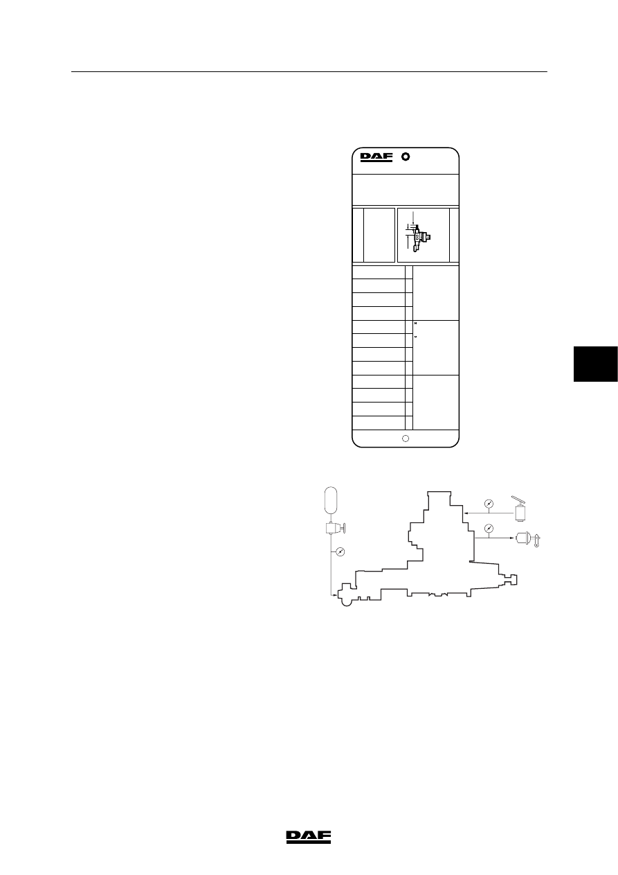
Explanatory notes on instruction plate
The information contained on the instruction
plate relates to the axle loads, the output
pressures and bellows pressures, in accordance
with the order of axles beneath the vehicle.
So “1” is the front axle, etc.
To check the load-dependent control valve, the
details on the instruction plate relating to the
“driven axle” are therefore vital.
L1 = Effective length of unloaded spring
between thrust piece and adjustable
plug. Spring length in mm.
L2 = bolt length up to counter nut in mm.
1.
Check whether the correct valve is fitted
(see instruction plate).
2.
Connect pressure gauge (4) to the test
connection of the load-dependent valve
(input pressure).
3.
Connect pressure gauge (2) to the test
connection on the rear axle brake cylinder
(output pressure).
4.
Connect pressure gauge (43) with a reducer
valve to the simulation connection of the
load-dependent valve (simulated adjustable
bellows pressure).
5.
Make sure that the reservoir pressure is
higher than 6.5 bar throughout the
measurement.
MEEREGELVENTIEL
EMPTY-LOAD VALVE
LAST-LEER VENTIEL
VALVE CHARGE-VIDE
VALVOLA VUOTO-CARICO
VALVULA VIDA-CARGA
ASLAST
AXLE LOAD
ACHSLAST
CHARGE SOUS ESSIEU
CARICO ASSE
CARGA EJE
UITGESTUURDE DRUK
DELIVERY PRESSURE
AUSGESTEUERTER DRUCK
PRESSION DELIVREE
PRESSIONE USCITA
PRESION DE SALIDA
G
p
2
BALGDRUK
PRESSURE BELLOWS
BALG DRUCK
PRESSION COUSSIN
PRESS.CUSCINI ARIA
PRESION FUELLES
p3
bar
bar
x 10
4
N
AUTOM. LASTAFHANKELIJKE REMKRACHTREGELING
AUTOM. LOAD SENSING DEVICE
AUTOM LASTABHANGIGE BREMSKRAFT REGELINR.
DISPOSITIF DE CORRECTION AUTOM DE FREINAGE
REGOLATORE AUTOM. DELLA FORZA FRENANTE
REGULADOR AUTOM. DEL ESFUERZO DE FRENADA
1263639
TYPE - TIPO : FA
W 475 711 071 0
p1= > 6.5 bar
p4= 6.0 bar
L1 = 114.0 MM L2 = 4.0 MM
2
1
2.0
2.5
3.0
4.0
10.0
11.5
12.0
13.0
2
1
1.4
1.5
1.6
2.0
4.6
5.3
5.5
5.9
4.3
4.4
4.4
4.5
5.8
5.9
5.9
6.0
2
1
0.3
0.5
0.7
1.2
4.1
4.8
5.1
5.6
0.2
0.4
L2
p1
p4
p3
L1
i = 1: 1.5
M6046
42
1
2
4
2
4
41
43
M6102
5
200424
Нет комментариевНе стесняйтесь поделиться с нами вашим ценным мнением.
Текст