DAF 95XF. Manual — part 75
2
Inspection and adjustment
XE ENGINE
3-5
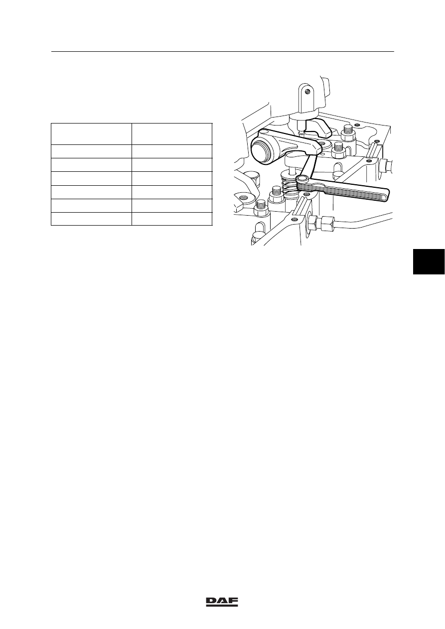
4.
By cranking the crankshaft always
1
/
3
stroke, using the special tool
(DAF no. 1310477), the valves can be
adjusted according to the injection
sequence 1-5-3-6-2-4.
Cylinder with valves
in overlap position
Adjust valves
of cylinder
1
6
5
2
3
4
6
1
2
5
4
3
5.
If the engine has been fitted with a DEB, the
DEB clearance must be checked following
the valve-clearance adjustment.
6.
Fit the valve cover, see
“Removal and installation”.
M200540
5
ǹ 0008
2
XE ENGINE
Inspection and adjustment
3-6
3.3 CHECKING AND ADJUSTING THE TIMING GEAR
Checking the timing gear
1.
Remove the valve cover from cylinders
1-2-3, see chapter “Removal and
installation”.
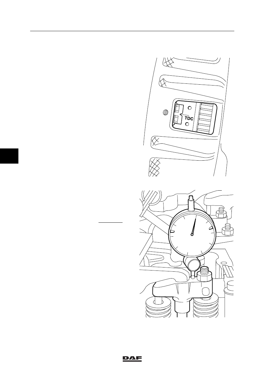
2.
Position cylinder 1 in the top dead centre
(TDC on the flywheel, cylinder 6 in rocking
position).
Note:
It is important that the bridges of the valve
mechanism are properly adjusted.
3.
Set the inlet valve clearance of the first
cylinder to 1 mm.
4.
Position the dial gauge on the inlet valve
bridge of the first cylinder, in such a way
that it measures in an exact vertical position
on the bridge and is capable of registering
an upward and downward measuring value
of 5 mm.
5.
Use the special tool (DAF no. 1310477) to
turn the crankshaft further in the direction of
rotation until the pistons of cylinders 1 and 6
have returned to the top dead centre (TDC).
6.
Read the dial gauge and compare the
measured value, see main group
“Technical data”.
Example
Pre-tension dial gauge
5.00 mm
Measured tension
4.65 mm
Valve opening
0.35 mm
Note:
If the valve opening matches that in the
technical data, it may be assumed that the
timing gear is properly set.
M200724
M200551
5
ǹ 0008
2
Inspection and adjustment
XE ENGINE
3-7
Adjustment, timing gear
1.
Remove the valve cover from cylinders
1-2-3, see chapter
“Removal and installation”.
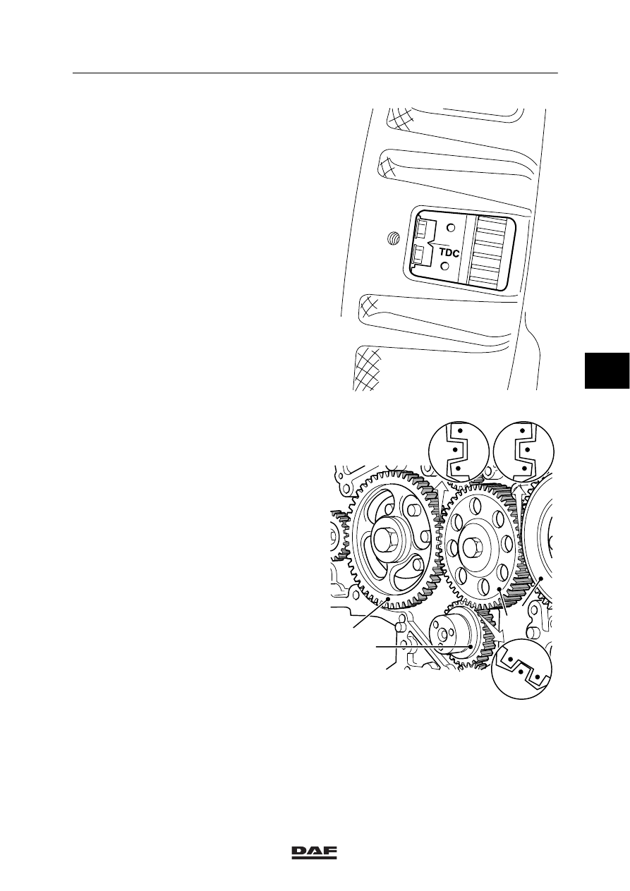
2.
Position cylinder 1 in the top dead centre
(TDC on the flywheel, cylinder 6 in rocking
position).
3.
Remove the timing-gear cover, see chapter
“Removal and installation”.
Note:
When the crankshaft (1) or the camshaft (2)
of an engine without intermediate gear
wheel (3) is rotated separately, the engine’s
pistons may touch the valves.
4.
Remove the intermediate gear wheel (3),
see “Removal and installation”.
5.
Rotate the camshaft gear wheel (2) in such
a position that the intermediate gear wheel
(3) can be installed in accordance with the
marks.
6.
Install the intermediate gear wheel and
tighten the attachment bolt to the specified
torque, see main group “Technical data”.
7.
Fit the timing-gear cover, see chapter
“Removal and installation”.
8.
Fit the valve cover, see
“Removal and installation”.
M200724
M200726
2
1
3
4
5
ǹ 0008
2
XE ENGINE
Inspection and adjustment
3-8
3.4 INSPECTION AND ADJUSTMENT, V-BELT TENSION
Check the V-belt by means of a belt-tension
gauge. The advantage of this method is a higher
measuring accuracy of the pre-tension, so that
the service life of the V-belt, among other things,
can be prolonged.
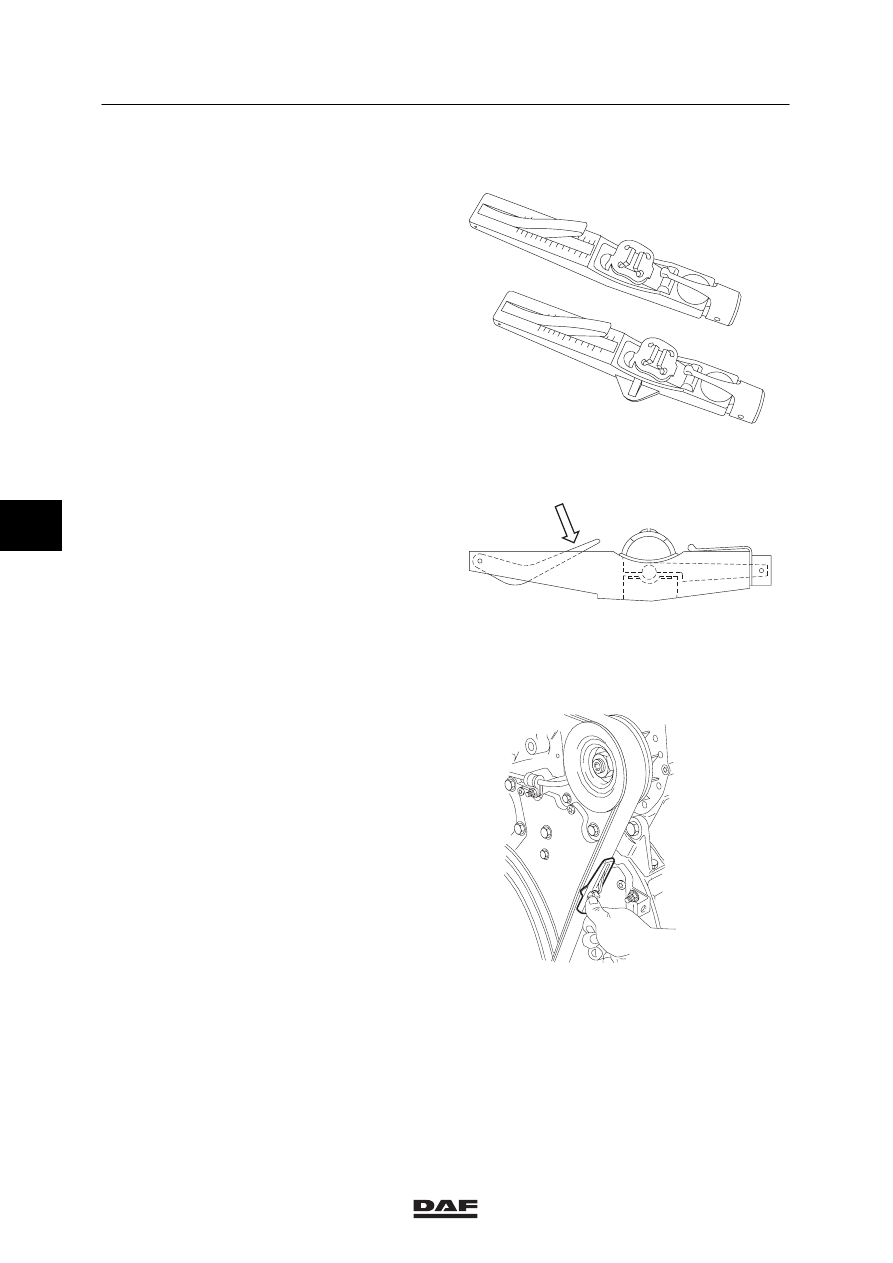
There are two versions: belt tension “Krikit I”,
to be used with the single belt version
(DAF no. 1240442), belt tension “Krikit II”
to be used with the twin belt version
(DAF no. 1240443).
The difference between belt-tension gauge
“Krikit I” and belt-tension gauge “Krikit II” is that
the latter has a larger belt support area.
Measuring with the “KRIKIT” belt-tension
gauge
1.
Set the gauge to zero by depressing the
measuring arm (1).
2.
Place the belt-tension gauge on the V-belt,
halfway between the alternator and the
crankshaft pulley.
3.
Slowly depress the V-belt by means of the
belt-tension gauge until a click is heard.
Then remove the belt-tension gauge
carefully. Take care that the gauge bar does
not move.
M2079
ABL
EU
ABL
EU
OPTIB
ELTI
N.200
600
LBS.50
150
100
200
300
LBS.100
1500
N.500
OPTIB
ELTII
1
M2061
M2091
5
ǹ 0008
Нет комментариевНе стесняйтесь поделиться с нами вашим ценным мнением.
Текст