DAF 95XF. Manual — part 310
5
Electrical installation
ELECTRICAL INSTALLATION
2-139
36
1316630/05
EL000146
1104
1104
29/402
1
380
4761
6
191
4760
5
191
4706
1104
4
191
1104
4761
4760
4706
18
189
17
189
16
189
4761
4760
4706
2630
2630
E117
2
19
4706
1181
35/402
2
380
1181
1181
1
276
1181
1181
5061
20
380
5061
6
277
4538
4538
5
197
4
197
4537
5062
5062
5
277
4
277
5061
5061
1181
B030
1
22
A042
1
42
1181
1181
1
196
1181
1181
1181
5118
6
380
5118
2630
1181
2609
8
189
2609
8
190
2609
D708
1
17
2609
2609
2609
10
483
E515
2
17
C063
1
17
2609
9
286
2609
9
383
2600
2600
5063
2600
4537
9
281
2600
2600
2600
C062
1
16
E514
1
16
2600
6
197
21
380
C733
B
17
C130
3
17
C149
3
17
2630
12
194
A040
594
D550
17/
232
D878
1010
1000
1010
1000
E030
10A
E182
15A
1
23456789
1
0
1
1
1
2
1
3
1
4
1
5
1
6
1
7
1
8
1
9
2
0
2
1
2
2
2
3
2
4
2
5
2
6
2
7
2
8
2
9
3
0
3
1
3
2
3
3
3
4
3
5
3
6
3
7
3
8
3
9
4
0
4
1
4
2
4
3
4
4
4
5
4
6
4
7
4
8
4
9
5
0
5
1
5
2
5
3
2/
394
8/
394
6/
394
10/
394
D862
1/
394
7/
394
5/
394
4/
394
3/
394
9/
334
308
31
B199
1
4
DL
3
DO
2
M
308
DO
31
B200
1
2
4
DL
3
M
0
C736
3
71
82
6
II
I
BA
B175
M
4
2
1
3
0
C803
5
17
II
I
BA
D853
5/
396
!
10
ǹ 9711
5
ELECTRICAL INSTALLATION
Electrical installation
2-140
36
1316630/05
EL000147
54
55
56
57
58
59
60
61
62
63
64
65
66
67
68
69
70
71
72
73
74
75
76
77
78
79
80
81
82
83
84
85
86
87
88
89
90
91
92
93
94
96
96
97
98
99
100
101
102
103
104
105
106
26/400
2
276
1208
1208
2
196
1208
1208
C695
4
18
1208
4521
4520
C696
4
18
1208
4523
6
276
4523
4
196
3
196
4520
4
276
4521
3
276
4520
4521
1208
1208
4521
4520
1208
8
276
4525
7
276
17/401
1207
1207
4522
5
276
4522
4524
4524
4525
4527
6
196
4527
1208
8
196
4525
7
196
1233
1233
4526
5
196
4526
4528
4528
4529
35/401
1233
1233
1233
1207
1207
1207
4525
C746
1
18
C744
2
53
4
1
C743
2
53
4
1
G029
30
85
86
87A
87
G028
30
85
86
87A
8
7
M
2
1
B004
C745
2
53
4
1
G031
30
85
86
87A
87
G030
30
85
86
87A
8
7
M
2
1
B003
D878
1010
1000
1010
1000
E044
10A
E033
15A
E034
15A
10
ǹ 9711
5
Electrical installation
ELECTRICAL INSTALLATION
2-141
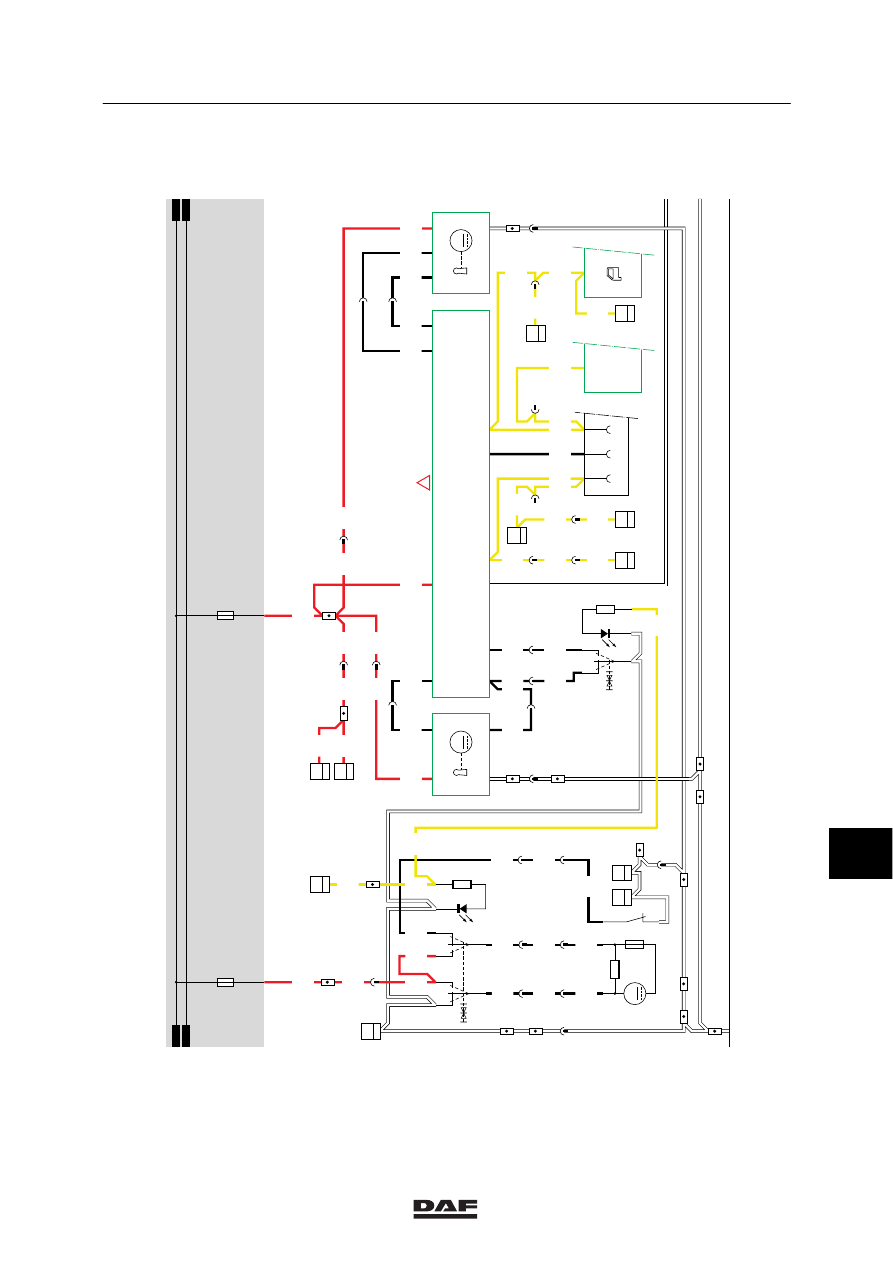
37. MECHANICAL LIFTING GEAR
Lifting:
A voltage is applied to the lifting gear switch
(C739), the electronic unit of the lifting gear
(D503) and the approximation switch for axle
load protection of lifting gear (10 tonnes) (E507)
through fuse E062 and wire 1221.
If the switch is switched into the ‘lifting’ position
(connection between points 3 and 1), valve
B071 (lifting-gear lifting valve) will be activated
through wire 4550. A voltage is also applied
through contacts 30 and 87a of relay G066
(lifting-gear take-over relay). As a result, the
lifting-gear motor relay (G052) will be activated,
thus activating the lifting-gear pump motor
(B073).
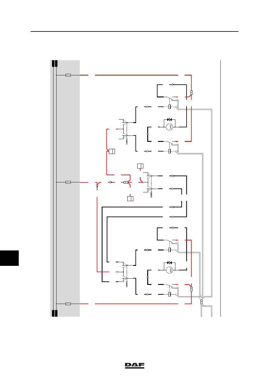
If the pressure has increased to 160 bar, the
control switch for lifting-gear oil-pressure limit
switch (E524) will be activated, thus activating
the lifting-gear take-over relay (G066) as a
result of which the contact of this relay will
switch from connection 30/87a to connection
30/87.
This will switch off the lifting-gear pump motor
(B073) and the pressure will fall to below
160 bar, so that the control switch for the
lifting-gear oil-pressure limit switch (E524) will
resume its neutral position.
If the switch on the dashboard is released, the
supply is disconnected and everything returns to
the starting position so that no more lifting takes
place.
Lowering:
Manual control:
A voltage is applied to the lifting gear switch
(C739), the electronic unit of the lifting gear
(D503) and the approximation switch for axle
load protection of lifting-gear (10 tonnes) (E507)
through fuse E062 and wire 1221. If the switch
is switched into the ‘lowering’ position
(connection between points 7 and 1), a voltage
will be applied to point S1 of the lifting gear’s
electronic unit (D503). This unit will apply a
voltage to point 87 for 2,5 minutes.
If within this 2,5 minute period the
dashboard switch is engaged again, the
electronic unit will reset and another 2,5
minute period will start.
10
ǹ 9711
5
ELECTRICAL INSTALLATION
Electrical installation
2-142
As a result, the lifting-gear motor relay (G052)
will also be activated, thus activating the
lifting-gear pump motor (B073). The motor is
activated through D623, relay G066 (connection
between points 30 and 87a) to connection point
85 of relay G052. At a pressure of 160 bar, the
oil-pressure limit switch (E524) switches off the
lifting-gear pump motor (B073) through relay
(G066) and relay (G052).
During the 2,5 minute period, the trailing axle
cannot be lifted as the 4/2 valve (B072) remains
activated. This valve should be in the
non-activated position (see hydraulics diagram).
Automatically:
If the axle pressure of the driven axle exceeds
10 tonnes, the trailing axle is lowered
automatically.
10-TONNES AXLE LOAD PROTECTION
If the driven rear axle is loaded with a weight of
10 tonnes or more, a signal is sent by the
approximation switch for axle load protection
(E507) to input S2 of the “lifting gear electronic
unit”. The signal sent by the approximation
switch for axle load protection (E507) to S2
should last for at least 10 seconds before the
lifting gear electronic unit (D503) will activate the
valve (B072) and the lifting-gear pump motor
(B073), so that the trailing axle is lowered. This
is to prevent the driven axle from exceeding the
legal maximum axle load maximum (10 tonnes).
VARIANTS
Location
5
This wire should be connected directly to
the battery.
10
ǹ 9711
Нет комментариевНе стесняйтесь поделиться с нами вашим ценным мнением.
Текст